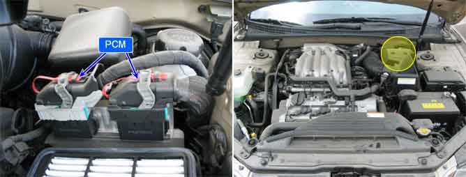
Several control units are applied to electronically controlled vehicles. These units perform each control with informations from various sensors. Thus, sharing signal information from sensors is needed, so CAN communication type whose communication speed is high and insensitive to electrical noise by spark generation is adopted to controlling power-train(PCM, TCM, ESP PCM, ABS PCM)
As sharing signals of engine speed, APS, gear shifting, torque reduction in ESP and various modules, active control is performed.
Checking CAN communication, under detecting condition, if an error within the detecting condition is detected for more than 1.5 sec., PCM sets U0001. MIL(Malfunction Indication Lamp) turns on when the malfunction lasts till consecutive 2 driving cycle.
Item | Detecting Condition | Possible cause |
DTC Strategy | ● Detects failures in communication between the PCM and another or modules in the vehicle which are on the CAN serial bus. | ● CAN BUS ● CAN communication module component |
Enable Conditions | ● Engine Run Time ≥ 2sec. ● Ignition Voltage ≥ 11V | |
Threshold value | ● CAN communicatin error | |
Diagnosis Time | ● Continuous | |
MIL On Condition | ● 2 Driving Cycles |
Communication Format | DIGITAL "0" | DIGITAL "1"( BUS IDLE ) | CAN Communication Line Resistance | |||
HIGH | LOW | HIGH | LOW | PCM | CAN RESISTER | |
CAN 2.0B | 3.5V | 1.5V | 2.5V | 2.5V | 120Ω (20°C) | 120Ω (20℃) |