
The Steering angle sensor(SAS) is joined to the multi function switch and using a CAN communication.
The SAS is composed of main gear, serve gear1 and serve gear2 to determine the turning direction.
If main gear is rotated according to the rotation of steering wheel serve gear1 and serve gear2, which is contact with main gear, will be rotated.
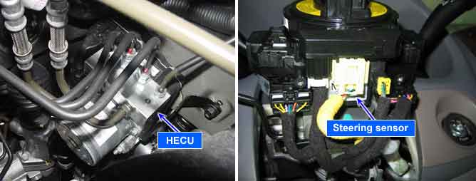
The HECU detects the absolute angle by using magnetic MR effect and the difference gear ratio of each serve gear and then send to the CAN comunication line.
The HECU detects the steering wheel’s operating speed and operating angle by using absolute angle, and this signal is used as a input signal of anti-roll control.
If the SAS signal is different from calculated value by yaw-rate sensor and wheel speed sensor, mechanically impossible SAS signal is detected, there is a difference between SAS signal and driving condition of the vehicle calculated from yaw-rate sensor and later G sensor, a failure is detected.
Item | Detecting Condition | Possible cause |
DTC Strategy | ● Signal Monitoring | ● Short of steering angle sensor circuit ● Faulty steering angle sensor ● Faulty HECU |
Case1 | Monitoring Period | ● Continuous |
Enable Conditions | ● During normal driving conditions the long time filtered driving direction is straight ahead. The long time filtered SAS-value is equivalent to the offset. If the offset value exceeds a threshold of approximately 15 deg a SAS-fault is determined. Failure detection time depends on the driving distance, vehicle speed and on the amount of failed SAS signal. Within 30 km of symmetrical driving the calculated offset corresponds to the sensor offset. | |
Case2 | Monitoring Period | ● Continous (If the following conditions are satisfied) 1. After SAS-initialization and vehicle reference speed > 1.4 m/s (5km/h) 2. No under voltage 3. At least one SAS-message was sent in the current 20ms-cycle. |
Enable Conditions | ● A SAS-gradient-failure is set, if 1. Signal gradient (steering angle velocity) from one 20 ms-cycle to another is higher than 40° or 2. Change of this gradient (steering angle acceleration) is higher than 15° : | (LwInK0K1 . LwInK1K2)| > 15° and | (LwInK0K1 + LwInK1K2)| > 15° - LwInK0K1 : Difference of the LWS-signal between the current 20ms-cycle and the last 20ms-cycle. - LwInK1K2 : Difference of the LWS-signal between the last 20ms-cycle and 20ms-cycle before. | |
Case3 | Monitoring Period | ● Continuous (After initialization and no under voltage detected) |
Enable Conditions | ● If value is higher than 665˚ + 90˚ tolerance for more than 300ms a fault is determined. | |
Case4 | Monitoring Period | ● Continuous (during driving) |
Enable Conditions | ● Based on a vehicle model a reference SAS signal is build. The difference between measured SAS signal and SAS signal calculated from yaw-rate sensor signal is evaluated for fault detection. Dependent on the driving conditions failures in size of [10 + 60 m/s / vehicle reference speed] deg at steering angle are recognized within 400 ~ 4800 ms through three possible recognition paths: 1. Curve Branch (lateral G > 2 m/s² and left and right curve driving) 2. Stability Branch (no large wheel speed differences and stable acceleration) 3. Straight ahead Branch (lateral G < 0.5 m/s² and yaw rate < 2 deg/s) The recognition time depends on the active branch (the time is shorter in a relation 1.:2.:3.-4:2:1) and the value of the permissible time threshold dependent on the deviation between the compared signals (small deviation → long detection time, large deviation → small detection time). | |
Case5 | Monitoring Period | ● Initialization once in every ignition cycle. ● The monitoring is active until a reset by a change in the SAS signal or until a right and left cornering can be recognized. |
Enable Conditions | ● If there is no change in the signal, but a right and left cornering has been recognized, a fault is determined. (lateral G > 2 m/s² in combination with a yaw rate > 6 °/s in both directions). - At a minimum change of e.g. 5° in the signal, the monitoring is reset. | |
Case6 | Monitoring Period | ● Continuous (during driving) |
Enable Conditions | ● The measured yaw rate and the yaw rates, calculated from the wheel speed sensor and SAS are compared. If the signals don’t fit and forwards driving is detected, a fault is determined. | |
Case7 | Monitoring Period | ● Continuous (during driving) |
Enable Conditions | ● Under normal conditions, two SAS messages are sent in one 20ms cycle, which is shown by an increase of the message counter by 2. If the message counter shows an increase higher than 3 or lower than 1 in one 20ms-cyle, a fault is stored after 160ms. | |
Fail Safe | ● Reduced controller function caused by faulty SAS signal. Allow the ABS/EBD control. ●The ESP warning lamp is activated. |