Is the problem found?

▶ Repair the trouble causing part and go to "Verification of Vehicle Repair".

▶ Go to "Power Circuit Inspection".
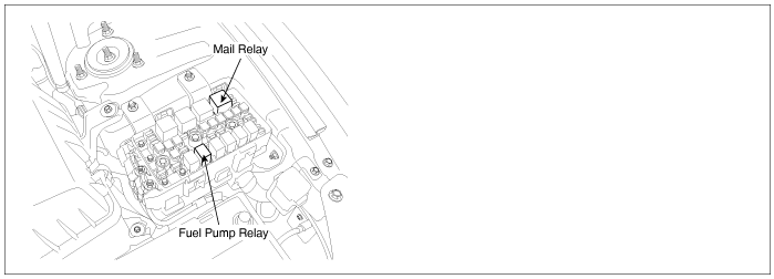
Main relay operates when Ignition ON signal is inputted to ECM connector(C244-K) terminal 28 and it supplies power to ECM, fuel pump relay, CMP, EGR actuator, throttle flap actuator, PTC heater relay and brake switch, etc. Especially, the power supplied to ECM is used as a main power of injectors, rail pressure control valve and ECM operation.
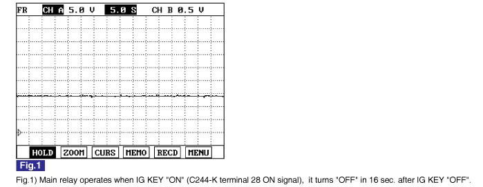
When IG KEY ON signal is shut off during turning engine OFF, ECM stops injector operation then engine turns OFF. Approx. after 16 sec., ECM shuts OFF main relay and system turns OFF.
Main relay is very important for engine operation, so careful inspection is strongly required.
When IG KEY OFF signal is imputted to ECM. ECM stops injector operation and engine turns OFF. Then, After-run(turning off process of ECM internal system) is performed in order to shut system down. During this process, if main relay power supply is cut too late or power supply is cut too early before After-run process completes, ECM detect main relay error and P0685 is set.
Item | Detecting Condition | Possible Cause | ||
DTC Strategy | ● Voltage monitoring | ● Main relay circuit ● Main relay component | ||
Enable Conditions | ● Engine running | |||
Threshold Value | ● When main relay respond to IG KEY - ON/OFF signal too fast or slow (After-run finished and it requires more than 2 sec. for Main relay to be deactivated.Main relay deactivated before After-run finished more than 3 times. ) | |||
Diagnostic Time | ● Immediately | |||
Fail Safe | Fuel cut | NO | ||
EGR Off | NO | |||
Fuel Limit | NO | |||
Check Lamp | NO | |||
Main Relay Coil Resistance | 80±10 Ω (20℃) |
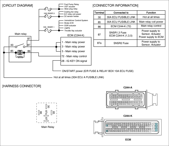
Electrical systems consist of a lot of harness and connectors, poor connection of terminals can cause various problems and damge of component.
Perform checking procedure as follows.
Check damage of harness and terminals : Check terminals for contact resistance, corrosion and deformation.
Check connecting condition of ECM and component connector : Check terminal seperation, damage of locking device and connecting condition between terminal and wiring.
Disconnect the pin which requires checking at male connector and insert it to the terminal at female connector for checking connecting condition. ( after checking, reconnect the pin at correct position. )
Is the problem found?

▶ Repair the trouble causing part and go to "Verification of Vehicle Repair".

▶ Go to "Power Circuit Inspection".
Check power circuit voltage
IG KEY "OFF", ENGINE "OFF".
Disconnect main relay.
Measure the voltage of main relay terminal 30 and 85.

Specification : 11.5V~13.0V
Is the measured voltage within the specification?

▶ Go to "Check power supply line(relay→actuator)" as follows.

▶ Repair E/R JUNCTION BOX 30A ECU RLY FUSIBLE LINK and related circuit and go to "Verification of Vehicle Repair".
Check power supply line(relay→actuator)
IG KEY "OFF", ENGINE "OFF".
Disconnect main relay and ECM connector.
Connect main relay terminal 30 and 87, 87a using jump wire.
Measure the voltage of ECM connector(C244-K) terminal 1,3,5.

specification : 11.5V~13.0V
Is the measured voltage within the specification?

▶ Go to "Control Circuit Inspection".

▶ Check and repair the open circuit where voltage can not be checked and go to "Verification of Vehicle Repair".
Check open in control circuit
IG KEY "OFF", ENGINE "OFF".
Disconnect main relay and ECM connector.
Check continuity between main relay terminal 86 and ECM connector(C244-K) 72.

specification : Continuity ( below 1.0Ω )
Is the measured resistance within the specification?

▶ Go to "2. Check short to ground in control circuit" as follows.

▶ Repair open in control circuit and go to "Verification of Vehicle Repair".
Check short to ground in control circuit
IG KEY "OFF", ENGINE "OFF".
Disconnect main relay and ECM connector.
Check continuity between main relay terminal 86 and chassis ground.
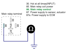
specification : Discontinuity ( Infinite Ω )
Is the measured resistance within the specification?

▶ Go to "3.Check short to battery in control circuit" as follows.

▶ Repair short to ground in control circuit and go to "Verification of Vehicle Repair".
Check short to battery in control circuit
IG KEY "OFF", ENGINE "OFF".
Disconnect main relay and ECM connector.
IG KEY "ON".
Measure the voltage of main relay connector terminal 86.
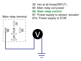
specification : 0.0V~0.1V
Is the measured resistance within the specification?

▶ Go to "Component Inspection".

▶ Repair short to battery in signal circuit and go to "Verification of Vehicle Repair".
Check main relay component resistance
IG KEY "OFF", ENGINE "OFF".
Disconnect main relay.
Measure the resistance between main relay coil component terminal 85 and 86.
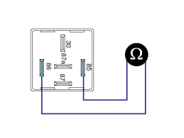
Specification : 80±10 Ω (20℃)
Is the measured resistance within the specification?

▶ Go to "2. Check main relay component operation" as follows.

▶ Replace main relay and go to "Verification of Vehicle Repair".
Check main relay component operation
IG KEY "OFF", ENGINE "OFF".
Disconnect main relay.
Supplies random B+ and ground to coil sides of main relay. ( terminal 85, terminal 86)
Check continuity between main relay component terminal 30 and 87, 87a.
specification : When power is supplied : Continuity ( below 1.0Ω )
When power is not supplied : Discontinuity ( Infinite Ω )
Is the continuity test within the specification?

▶ Go to "Verification of Vehicle Repair".

▶ Replace main relay and go to "Verification of Vehicle Repair".
※ Repeat this process 2~3 times.
After a repair, it is essential to verify that the fault is corrected.
After connecting Scantool select "DIAGNOSTIC TROUBLE CODES(DTCs)" mode.
Clear recorded DTC using Scantool.
Drive the vehicle within DTC "Enable conditions" in "General information".
After selecting "DIAGNOSTIC TROUBLE CODES(DTCs)" mode and check if DTC is recorded again.
Are any DTCs recorded ?

▶ Go to the DTC guide of recorded NO. in Scantool.

▶ System operates within specification.