Monitor "BOOST PRESSURE SENSOR" parameter on the Scantool.
Specification : 1000hpa ± 100hpa(VGT actuator : approx. 76%) at idle
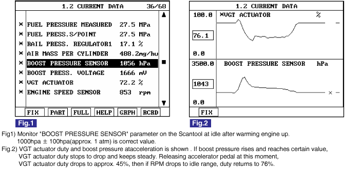
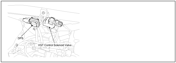
VGT(Variable Geometric Turbocharger) is the device which increases the efficiency of turbocharger at low rpm and lasts optimum turbo efficiency at high rpm as varying the cross sectional area through which exhaust gas passes turbocharger impeller. It relieves turbo lag at low speed and increse engine power generation.Engine speed, APS signal, MAFS and Boost pressure sensor information is inputted to ECM. ECM actuates vacuum diafragm which controls exhaust gas line as controlling VGT actuator duty to maintain optimum state of air compression.
P0048 is set when excessive current is detected in VGT actuator control circuit for more than 1 sec.. This code is due to short to battery in control circuit or internal short of VGT actuator component.
Item | Detecting Condition | Possible Cause | ||
DTC Strategy | ● Signal monitoring | ● VGT actuator circuit ● VGT actuator component | ||
Enable Conditions | ● IG KEY "ON" | |||
Threshold Value | ● Short to battery | |||
Diagnostic Time | ● 1 sec. | |||
Fail Safe | Fuel cut | NO | ||
EGR Off | YES | |||
Fuel Limit | YES | |||
Check Lamp | YES | |||
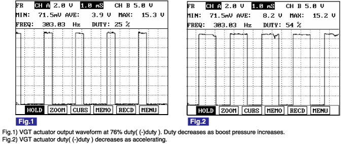
VGT actuator component resistance | VGT actuator operating Hz | VGT actuator operating duty |
14.7 ~ 16.1Ω (20℃) | 300Hz | 76% at idle, decreases as accelerating |
Connect Scantool to Data Link Connector (DLC).
Warm engine up to normal operating temperature.
Turn "OFF" electrical devices and A/C.
Monitor "BOOST PRESSURE SENSOR" parameter on the Scantool.
Specification : 1000hpa ± 100hpa(VGT actuator : approx. 76%) at idle

Electrical systems consist of a lot of harness and connectors, poor connection of terminals can cause various problems and damge of component.
Perform checking procedure as follows.
Check damage of harness and terminals : Check terminals for contact resistance, corrosion and deformation.
Check connecting condition of ECM and component connector : Check terminal seperation, damage of locking device and connecting condition between terminal and wiring.
Disconnect the pin which requires checking at male connector and insert it to the terminal at female connector or checking connecting condition. ( after checking, reconnect the pin at correct position. )
Is the problem found?

▶ Repair the trouble causing part and go to "Verification of Vehicle Repair".

▶ Go to "Power Circuit Inspection".
Check power circuit voltage
IG KEY "OFF", ENGINE "OFF"
Disconnect VGT actuator connector
IG KEY "ON"
Measure the voltage of terminal 2 of VGT actuator.
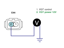
Specification : 11.5V~13.0V
Is the measured voltage within the specification?

▶ Go to "Control Circuit Inspection".

▶ Repair E/R JUNCTION BOX 15A SNSR2 FUSE and related circuit and go to "Verification of Vehicle Repair".
Check monitoring voltage in control circuit
IG KEY "OFF", ENGINE "OFF"
Disconnect VGT actuator connector
IG KEY "ON"
Measure the voltage of terminal 1 of VGT actuator.
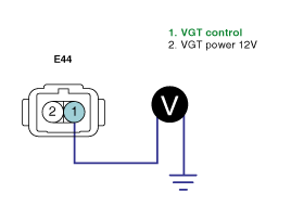
Specification : 3.2V~3.7V
Is the measured voltage within the specification?

▶ Go to "Component Inspection".

▶ When voltage is not detected : Go to "2. Check open in control circuit" as follows.
▶ When high voltage is detected : Repair short to battery and go to "Verification of Vehicle Repair".
Check open in control circuit
IG KEY "OFF", ENGINE "OFF"
Disconnect VGT actuator connector and ECM connector.
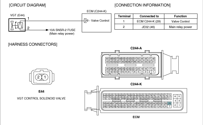
Check continuity between VGT actuator connector terminal 1 and ECM connector(C244-K) terminal 29.

specification : Continuity ( below 1.0Ω )
Is the measured resistance within the specification?

▶ Repair short to ground and go to "Verification of Vehicle Repair".

▶ Repair open in control circuit and go to "Verification of Vehicle Repair".
Check VGT actuator component resistance
IG KEY "OFF", ENGINE "OFF"
Disconnect VGT actuator connector.
Measure the resistance between VGT actuator component terminal 1 and 2.
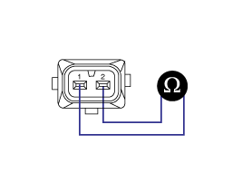
Specification : 14.7 ~ 16.1Ω (20℃)
Is VGT actuator component resistance within the specification?

▶ Go to "2.Check VGT actuator operation" as follows.

▶ Replace VGT actuator and go to "Verification of Vehicle Repair".
Check VGT actuator operation
IG KEY "ON", ENGINE "ON".
Check that VGT actuator operating duty is 76% after warming engine up.
Check if vacuum generates after disconnecting VGT valve vacuum hose.
Check if vacuum generates when decelerating after rapid acceleration (Vacuum must not generates, correct VGT actuator operating duty is 45%).
Specification : VGT actuator duty 76% : vacuum generates
VGT actuator duty 45% : vacuum does not generate
Does vacuum state changes correctly depending on the change of VGT actuator operating duty?

▶ Go to "Verification of Vehicle Repair".

▶ Replace VGT actuator and go to "Verification of Vehicle Repair".
※ Repeat this process 2~3 times.
After a repair, it is essential to verify that the fault is corrected.
After connecting Scantool select "DIAGNOSTIC TROUBLE CODES(DTCs)" mode.
Clear recorded DTC using Scantool.
Drive the vehicle within DTC "Enable conditions" in "General information".
After selecting "DIAGNOSTIC TROUBLE CODES(DTCs)" mode and check if DTC is recorded again.
Are any DTCs recorded ?

▶ Go to the DTC guide of recorded NO. in Scantool.

▶ System operates within specification.