Measure resistance between ETC module terminals 7 and 6 (TPS 2).
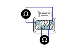
Specification: Refer to SPECIFICATION.
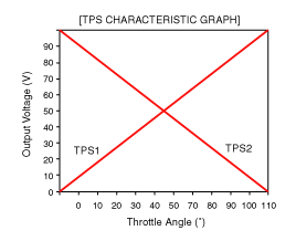
Throttle Angle(˚) | Output Voltage(V) [Vref = 5.0V] | |
TPS1 | TPS2 | |
0˚ | 0V | 5.0V |
10˚ | 0.5V | 4.5V |
20˚ | 0.9V | 4.1V |
30˚ | 1.4V | 3.6V |
40˚ | 1.8V | 3.2V |
50˚ | 2.3V | 2.7V |
60˚ | 2.7V | 2.3V |
70˚ | 3.2V | 1.8V |
80˚ | 3.6V | 1.4V |
90˚ | 4.1V | 0.9V |
100˚ | 4.5V | 0.5V |
110˚ | 5.0V | 0V |
Item | Sensor Resistance |
TPS1 | 4.0 ~ 6.0㏀ at 20℃ (68℉) |
TPS2 | 2.7 ~ 4.1㏀ at 20℃ (68℉) |
Item | Sensor Resistance |
Coil Resistance (Ω) | 1.275 ~ 1.725Ω at 20℃ (68℉) |
Mode | Description | Symptom | Possible Cause | |
MODE 1 | FORCED ENGINE SHUTDOWN | Engine stop | ● ETC system can't proceed reliable algorithm procedure
| |
MODE 2 | FORCED IDLE & POWER MANAGEMENT | Forced idle state controlled by fuel quantity regulation and ignition timing adjustment | ● ETC system can't control engine power via throttle device ● Disabled throttle control or broken throttle position information | |
MODE 3 | FORCED IDLE | Forced idle state and no response for accelerator activation | ● No information about the accelerator position
| |
MODE 4 | LIMIT PERFORMANCE & POWER MANAGEMENT | Engine power is determined by accelerator position and idle power requirement (Limited vehicle running) | ● ETC system can't securely control engine power | |
MODE 5 | LIMIT PERFORMANCE | 1. Engine power varies with accelerator position, but driver perceives lack of engine power. 2. MIL ON (Normal vehicle running) | ● Not reliable accelerator position signal or bad maximum power generation
| |
MODE 6 | NORMAL | Normal |
Connect a scan tool to the Diagnoisis Link Connector (DLC).
Start engine and check output voltages of TPS 1 and 2 at C.T and W.O.T.
Condition | Output Voltage (V) | |
TPS 1 | TPS 2 | |
C.T | 0.25 ~ 0.9V | Min. 4.0V |
W.O.T | Min. 4.0V | 0.25 ~ 0.9V |
Turn ignition switch OFF and disconnect the scantool from the DLC.
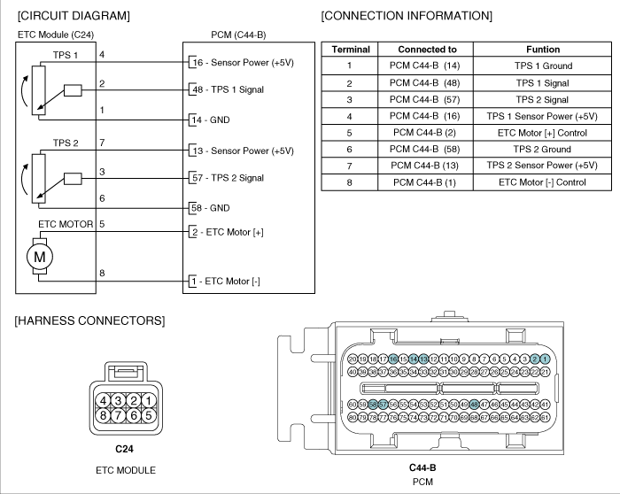
Disconnect ETC module connector and measure resistance between ETC module terminals 4 and 1 (TPS 1).
Measure resistance between ETC module terminals 7 and 6 (TPS 2).

Specification: Refer to SPECIFICATION.
Disconnect ETC module connector and measure resistance between ETC module terminals 5 and 8.
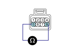
Specification: Refer to SPECIFICATION.
Erase DTC(s) memorized in PCM with a scan tool.
Turn ignition switch off and wait for about 10 seconds.
Turn ignition switch on for more then 1 second. (At this time, the PCM records initial position of ETC motor on its EEPROM).