3.
Has a problem been found?

▶ Repair as necessary and then go to "Verification of Vehicle Repair" procedure.

▶ Go to "Power Circuit Inspection" procedure.
Driver can inhibit the ESP control by ESP switch. When switch signal send into HECU, ESP warning lamp go ON and ESP control is stopped and if next switch signal is inputted again, ESP control is ready. This function is used for sporty driving or vehicle inspection.
Trouble code is set when the condition that the level of ESP switch is high is continued for 60sec.When the ESP switch failure is set there is no signal in the warning lamp and HECU inhibit the ESP control and allow the ABS/EBD control.
Item | Detecting Condition | Possible cause |
DTC Strategy | ● Short circuit monitoring | ● Open or short ESP switch ● Faulty ESP switch |
Monitoring Period | ● Continuous | |
Enable Conditions | ● When the ESP switch is ON for 60 sec. | |
Fail Safe | ● Inhibit the ESP control and allow the ABS/EBD control. Meanwhile, stop checking the ESP switch failure under the ESP control. ● The ESP warning lamps are activated. |
Many malfunctions in the electrical system are caused by poor harness(es) and terminals. Faults can also be caused by interference from other electrical systems, and mechanical or chemical damage.
Thoroughly check connectors for looseness, poor connection, bending, corrosion, contamination, deterioration, or damage.
Has a problem been found?
▶ Repair as necessary and then go to "Verification of Vehicle Repair" procedure.
▶ Go to "Power Circuit Inspection" procedure.
Ignition "ON" & Engine "OFF" & ESP Switch"ON".
Measure voltage between terminal "31" of the HECU harness connector and chassis ground.
Specification : Approx B+
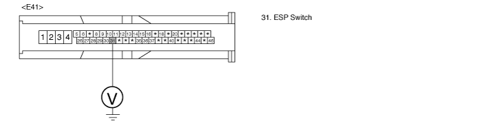
Is the measured voltage within specifications?
▶ Fault is intermittent caused by open or short in ESP switch line, faulty ESP switch or was repaired and HECU memory was not cleared. Go to the applicable troubleshooting procedure.
▶ Check for damaged harness and poor connection in the power harness between the battery terminal(+) and the terminal "31" of the HECU harness connector . Check for open or blown 10 A fuse referring to "Circuit Diagram" . Repair as necessary and then go to "Verification of vehicle Repair" procedure.
Ignition "ON".
Disconnect ESP switch connector.
Press the ESP switch.
Measure resistance between terminal "3" of the ESP switch harness connector and terminal "4" of the ESP switch harness connector.
Specification : Approx. below 1 Ω
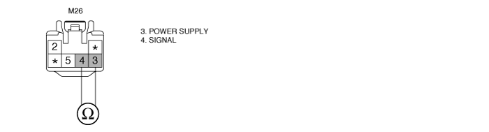
Is the measured resistance within specifications?
▶ Fault is intermittent caused by faulty ESP switch or was repaired and HECU memory was not cleared. Go to the applicable troubleshooting procedure.
▶ Substitute with a known-good ESP switch and check for proper operation. If problem is corrected, replace ESP switch and then go to "Verification of Vehicle Repair" procedure.
After a repair, it is essential to verify that the fault has been corrected.
Connect scantool and select "Diagnostic Trouble Codes(DTCs)" mode
Using a scantool, Clear DTC.
Operate the vehicle within DTC Detecting Condition in General Information.
Are any DTCs present ?
▶ Go to the applicable troubleshooting procedure.
▶ System performing to specification at this time.
