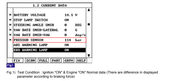
Monitor the "Pressure sensor" parameter on the Scantool.
Specification : Approx. 60 bar ~150 bar (There are difference in displayed parameter according to braking force)


The pressure sensor, installed in the HECU, sense the brake oil pressure to judge driver's brake intention when ESP is operating. If pressure of master cyclinder is applied to pressure sensor, the strain of the piezo element is changed and then the resistance of brige circuit is chanded according to changed strain. Therefore this changed resistance changes output voltage of brige circuit and output voltage changes linerly. The sensor output is a analog signal in proportion to supply voltage, and the HECU recognizes a pressure value according to signal ratio about supply voltage.
Each unfiltered input signal voltage is monitored to be in the range of 4.7 V < input signal voltage < 5.3 V. A failure is detected if the output signal value is out of specified range for more than 100 ms or pressure sensor self test form is against to specification during self test.
Item | Detecting Condition | Possible cause | |
DTC Strategy | ● Voltage Monitoring | ● Open or short of pressure sensor circuit ● Faulty pressure sensor ● Faulty HECU | |
Case 1 | Monitoring Period | ● Continuous | |
Enable Conditions | ● A sensor supply failure is detected if Sensor Supply Voltage > 5.3 V or Sensor Supply Voltage < 4.7 V for t >= 60 ms. | ||
Case 2 | Monitoring Period | ● Continuous | |
Enable Conditions | ● A Fault is set if the DSO signal is voltage of DSO > 4.7 V or voltage of DSO < 0.3V for a time t >= 100 ms. - DSO : original pressure value. | ||
Case 3 | Monitoring Period | ● Continuous | |
Enable Conditions | ● A Fault is set if the DSI signal is voltage of DSI > 4.7 V or voltage of DSI < 0.3V for a time t >= 100 ms. - DSI : inverted pressure value. | ||
Case 4 | Monitoring Period | ● Continuous | |
Enable Conditions | ● A Fault is set if the voltage of DSO + DSI > 5.5V or voltage of DSO + DSI < 4.5V for a time t >= 100ms. - DSO : original pressure value. - DSI : inverted pressure value. | ||
Case 5 | Monitoring Period | ● Once during Power Up | |
Enable Conditions | ● POS detects internal sensor malfunctions (sensor element, amplification, etc.). The POS is triggered if no low voltage is present and supply voltage is switched on. The test phase is divided in two 60 ms parts. DSO signal must be < 0.5 V for 30 ms. In phase 2 DSO signal must be between 1.9V and 3.1V for also 30 ms then the POS Test is passed. The test phase is divided in two 60 ms parts. DSO and DSI signal must be < 0.5 V for 30 ms. In phase 2 DSO and DSI signal must be between 1.9 V and 3.1 V for also 30 ms then the POS Test is passed. A fault is set if POS does not satisfy the above conditions - POS : Power on selftest. | ||
Fail Safe | ● No Pressure Signal available.. ● Sensor failure outside the ABS control cycle - Only the ABS/ESP functions are inhibited, allow the EBD. The ABS/ESP warning lamps are activated and the EBD warning lamp is not activated. ● Sensor failure inside the ABS control cycle - Inhibit the ESP control, allow the EBD. The ESP warning lamps are activated. After the control, the ABS functions are inhibited. The ABS warning lamps are activated. | ||
Connect scantool to Data Link Connector(DLC).
Ignition "ON" & Engine "ON".
Press the brake pedal.
Monitor the "Pressure sensor" parameter on the Scantool.
Specification : Approx. 60 bar ~150 bar (There are difference in displayed parameter according to braking force)

Whenever brake pedal is pushed down, is the pressure sensor's scantool data changed?

▶ Fault is caused by having been repaired and HECU memory was not cleared. Clear the DTC and then go to "Verification of Vehicle Repair" procedure.

▶ Go to "Component Inspection" procedure.
Ignition "OFF".
Engine "ON".
Does warning lamp remain On?

▶ Substitute with a known-good HECU and check for proper operation. If problem is corrected, replace HECU and then go to "Verification of Vehicle Repair" procedure.

▶ Fault is intermittent caused by open or short of wheel speed sensor harness, faulty wheel speed sensor. Go to the applicable troubleshooting procedure.
After a repair, it is essential to verify that the fault has been corrected.
Connect scantool and select "Diagnostic Trouble Codes(DTCs)" mode
Using a scantool, Clear DTC.
Operate the vehicle within DTC Detecting Condition in General Information.
Are any DTCs present ?

▶ Go to the applicable troubleshooting procedure.

▶ System performing to specification at this time.