Monitor "CAM, Engine speed" on service data.

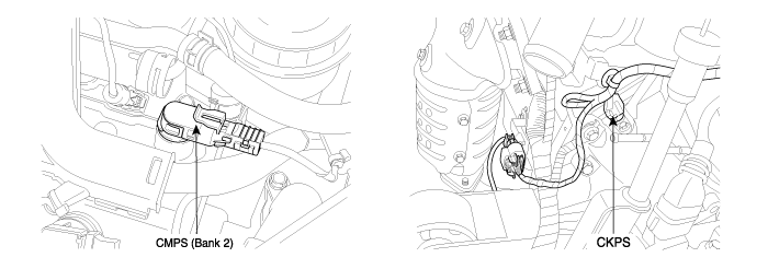
Different from the existing fixed cam phase angle type, CVVT(Continuously Variable Valve Timing) is the device which varies cam phase angle continuously to be optimum. And with engine oil pressure, it operates. CVVT consists of OCV(Oil Control Valve) and cam phaser. OCV, mounted on cylinder head, controlls the amount and direction of oil delivered to cam phaser by oil valve which is connected to a solenoid. Cam phaser, rotating cam phaser rotor with pressure and amount of oil produced by OCV, rotates cam shaft forcefully for or against the rotating direction and finally, cam shaft phase changes. With the appliance of CVVT, engine power,fuel efficiency and the quality of exhause gas are improved.
Tooth offsets are learned, updated, stored and initialized. For a given cam target wheel and systemcalibration, the tooth offsets should maintain relatively steady values. If the values of tooth offsets are observed to drift outside of an established range, then a failure is present for measuring cam phasing.
This diagnosis is to verify that learned tooth offsets are within an acceptable range.
PCM monitors tooth offset while no active faults is present. If the tooth offsets is out of threshold during more than 6 offset learning for 36 offset learning, PCM determines that a fault exists and a DTC is stored.
Item | Detecting Condition | Possible cause | |
DTC Strategy | ● Determines if CAM(B2) target is aligned correctly to crank | ● CKPS, CMPS(B2) ● CVVT ● Timing Misalignment ● PCM | |
Enable Conditions | ● No active faults | ||
Thresh old value | Case 1 | ● Real Offset Value〈 Min. Cam Offset programmed in PCM | |
Case 2 | ● Real Offset Value 〉Max. Cam Offset programmed in PCM | ||
Diagnosis Time | ● Continuous (More than 6 offset learning failure for 36 offset learning ) | ||
MIL On Condition | ● 2 driving Cycles | ||

Connect scantool and warm -up the engine until normal operating temperature.
Monitor "CAM, Engine speed" on service data.

Are the "CMPS(B2) & Engine RPM" data displayed correctly ?

▶ Fault is intermittent caused by poor contact in the sensor’s and/or PCM’s connector or was repaired and PCM memory was not cleared. Thoroughly check connectors for looseness, poor connection, bending, corrosion, contamination, deterioration, or damage. Repair or replace as necessary and go to "Verification of Vehicle Repair" procedure.

▶ Go to "Terminaal and connector inpection" procedure.
Many malfunctions in the electrical system are caused by poor harness and terminals. Faults can also be caused by interference from other electrical systems, and mechanical or chemical damage.
Thoroughly check connectors for looseness, poor connection, bending, corrosion, contamination, deterioration, or damage.
Has a problem been found?

▶ Repair as necessary and go to "Verification of Vehicle Repair" procedure.

▶ Go to "System Inspection" procedure.
Check CMPS
IG "OFF" & Disconnect CMPS connector.
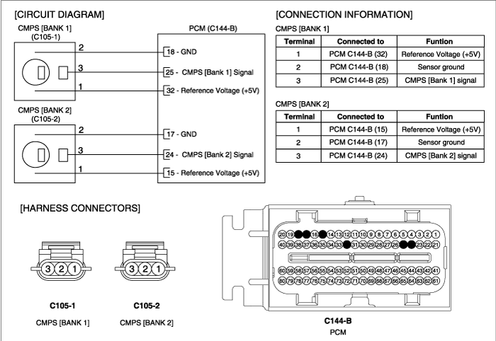
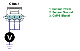
IG "ON" & Measure voltage between terminal 1,2 & 3 of CMPS(B2) harness connector and chassis ground.
Specification :
Terminal 1. approx. 5V
Terminal 2. approx. below 1V
Terminal 3. approx. 5V
Is the measured voltage within specification ?

▶ Go to Check "CKPS" as follow.

▶ Repair or replace as necessary and then go to " Verification of Vehicle Repair" procedure.
Check CKPS
IG "OFF" and disconnect CKPS connector.
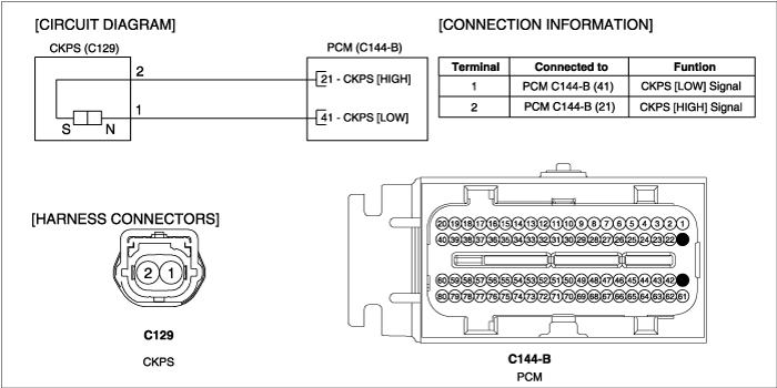
IG "ON" & Measure voltage between terminal 1 & 2 of CKPS harness connecotor and chassis ground.
Specification : Approximately 1.4V
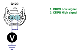
Is the measured voltage within specification ?

▶Go to "component Inspection" procedure.

▶Repair or replace as necessary and then go to "Verification of Vehicle Repair" procedure.
CMPS, CKPS Inspection
IG "OFF" and connect scantool.
ENG "ON" and Measure signal waveform at terminal 3 of CMPS.
Measure signal waveform at terminal 1 or 2 of CKPS.

Is the measured signal waveform O.K ?

▶ Substitute with a known - good PCM and check for proper operation. If the problem is corrected, replace PCM and go to "Verification of Vehicle Repair" procedure.
There is a memory reset function on scantool that can erase optional parts automatically detected and memorized by PCM.
Before or after testing PCM on the vehicle, use this function to reuse the PCM on the others

▶ Go to "Timing Mark Inspection" procedure as follow.
Timing Mark Inspection
IG "OFF" and check the timing mark is correctly aligned.
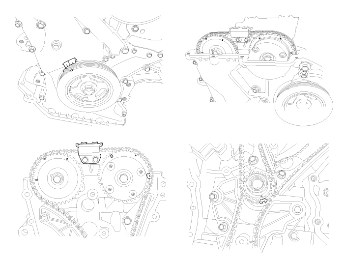
Is the timing mark correctly aligned ?

▶ Substitute with a known - good CVVT and check for proper operation. If the problem is corrected, replace CVVT and go to "Verification of Vehicle Repair" procedure.

▶ Repair or replace as necessary and then, go to "Verification of Vehicle Repair" procedure.
After a repair, it is essential to verify that the fault has been corrected.
Monitor and record the Freeze Frame Data for the Diagnostic Trouble Code(DTC) which has been diagnosed.
Using a Scantool, Clear the DTCs
Operate the vehicle within conditions noted in the freeze frame data or enable conditions
Monitor that all rediness test have been verified as " Complete "
Are any DTCs present ?

▶ Go to the applicable troubleshoooting procedure.

▶ System is performing to specification at this time.