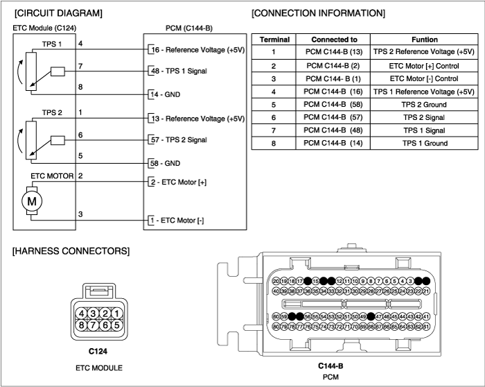
ETC(Electronic Throttle Control Valve) is the device controlling amount of air to engine acccording to driver's intension. Different from the existing mechanical throttle valve which is composed of accelerator pecal and connecting wire cable, ETC consists of a motor, a throttle body and a throttle position sensor. Receiving input signals from electronic accelerator pedal module, PCM lets ETC motor control throttle valve. With ETC, cruise control system works without any additional device.
Comparing real intake air flow and the intake air flow calculated by ETS, under detecting condition, if the difference of air flow more than threshold is detected for more than 3.9 sec., PCM sets P2173. MIL(Malfunction Indication Lamp) turns on when the malfunction lasts till 1 driving cycle.
Item | Detecting Condition | Possible Cause | |
DTC Strategy | ● The engine airflow measurements not based on throttle position are compared with throttle position based estimated airflow. | ● Air Leakage between TPS and MAFS ● Faulty throttle body ● Faulty PCM | |
EnableConditions | ● Engine running ● Throttle Actuation Mode is not OFF ● MAP Sensor is not failed ● MAF Sensor is not failed ● IAT sensor is not failed | ||
Threshold | Case 1 | ● Speed-Density Airflow - ETC estimated airflow 〉 9 g/s | |
Case 2 | ● MAF reading - ETC estimated airflow 〉 7g/s | ||
Diagnosis Time | ● Contineous (More than 3.9sec. Failure for every 15.6sec. Test) | ||
MIL On Condition | ● 1 Driving Cycle |
Air flow (kg/h) | Frequency (Hz) |
0 kg/h | 720 ~ 880 Hz |
12.6 kg/h | 2,595 Hz |
18.0 kg/h | 2,930 Hz |
23.4 kg/h | 3,208 Hz |
32.4 kg/h | 3,609 Hz |
43.2 kg/h | 3,975 Hz |
57.6 kg/h | 4,361 Hz |
72.0 kg/h | 4,683 Hz |
108.0 kg/h | 5,362 Hz |
144.0 kg/h | 5,885 Hz |
198.0 kg/h | 6,527 Hz |
270.0 kg/h | 7,219 Hz |
360.0 kg/h | 7,945 Hz |
486.0 kg/h | 8,736 Hz |
666.0 kg/h | 9,660 Hz |
900.0 kg/h | 10,613 Hz |
Throttle opening (°) | Output voltage(V) [Vref=5.0V] | |
TPS1 | TPS2 | |
0° | 0.0V | 5.0V |
10° | 0.5V | 4.5V |
V20° | 0.9V | 4.1V |
30° | 1.4V | 3.6V |
40° | 1.8V | 3.2V |
50° | 2.3V | 2.7V |
60° | 2.7V | 2.3V |
70° | 3.2V | 1.8V |
80° | 3.6V | 1.4V |
90° | 4.1V | 0.9V |
100° | 4.5V | 0.5V |
110° | 5.0V | 0.0V |
Pressure(kPa)(kPa) | Output voltage(V) |
20.0kPa | 0.79V |
35kPa | 1.382V |
46.66kPa | 1.84V |
60kPa | 2.369V |
90kPa | 3.75V |
101.32kPa | 4.00V |
Connect scantool to DLC.(Data Link Connector)
Warm up the engine to normal operating temperature.
Monitor "TPS1&2, MAPS,MAFS" parameters on scantool
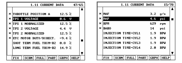
▶Fault is intermittent caused by poor contact in Sensor’s and/or PCM’s connector or was repairedand PCM memory was not cleared. Thoroughly check connectors for looseness, poorconnection, bending, corrosion, contamination, deterioration, or damage. Repair or replaceas necessary and go to "Verification of Vehicle Repair" procedure
▶Go to "System Inspection" procedure.
Visual Inspection
Check the air hose between MAFS and throttle body is torn or installation.
Check deforamtion, crack or installation of throttle valve(body)
Has a problem been found ?
▶ Substitute with a known-good Air hose or throttle body and check for proper operation.
If the problem is corrected,replace air hose or throttle body and then go to "Verification of Vehicle Repair" procedure.
▶ Substitute with a known-good PCM and check for proper operation. If the problem is corrected,replace PCM and then go to "Verification of Vehicle Repair" procedure.
There is a memory reset function on scantool that can erase optional parts automaticallydetected and memorized by PCM.
Before or after testing PCM on the vehicle, use this function to reuse the PCM on the others
Erase the trouble codes on PCM
Turn the ignition key off and keep this condition until the main relay is turned off.(It will takes 10sec.)
Turn ignition key on more than 1second to record the throttle motor position on the EEPROM
After a repair, it is essential to verify that the fault has been corrected.
Monitor and record the Freeze Frame Data for the Diagnostic Trouble Code(DTC) which has been diagnosed.
Using a Scantool, Clear the DTCs
Operate the vehicle within conditions noted in the freeze frame data or enable conditions
Monitor that all rediness test have been verified as " Complete "
Are any DTCs present ?
▶ Go to the applicable troubleshoooting procedure.
▶ System is performing to specification at this time.