3.
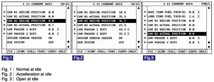
Monitor "Cam Duty2, Cam Desired Position(B2) and Cam Actual Position(B2)" on the service data.
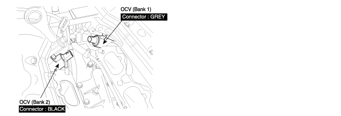
PCM controls OCV(Oil Contol Valve) with PWM (Pulse Width Modulator) signal to change oil passages supplying oil to CVVT that makes CAM postion changes (advance or retard). OCV is integrated with oil filter and located at the nearest CVVT on the engine block.
As the cam phaser is advanced and retarded, its position is measured using a toothed wheel.
The wheel is attached to the camshaft, or to the cam phaser rotor. A sensor picks up the signal from the wheel and its output is read by the engine control unit. A cam signal is generated for each cam phaser on the engine. This requires a separate toothed wheel and cam sensor combination for each cam phaser. The cam signal and crankwheel signal are compared as the engine turns, and the phasing position is determined. The position is displayed in crank angle degrees, relative position from default. This position measurement is used as feedback for the position control software, which determines the required percent duty cycle commanded to the oil control valve.
When the enable condition is satisfied, the PCM checks that OCV outputs (Voltage level) are observed when OCVs are commanded. When a OCV output failure is detected, the appropriate fail counter is incremented.
If the failure threshold is exceeded 5 seconds during one diagnostic test(10second), the test is failed and DTC is stored. MIL(Malfunction Indication Lamp) turns on when the malfunction lasts till consecutive 2 driving cycle.
Item | Detecting Condition | Possible cause | |||||
DTC Strategy | ● Detects a short to ground or open circuit of OCV circuit | ● Poor Connection ● Open in Power circuit ● Open or short to ground in Control Circuit ● OCV ● PCM | |||||
Enable Conditions | ● No disabling Faults Present ● Engine Running ● 11V ≤ Ignition Voltage ≤ 16V ● Enable Time delay ≥ 0.5sec | ||||||
Threshold value | ● Short to ground or open circuit | ||||||
Diagnosis Time | ● Continuous (More than 5 seconds failure for every 10 seconds test ) | ||||||
MIL On Condition | ● 2 Driving Cycles | ||||||
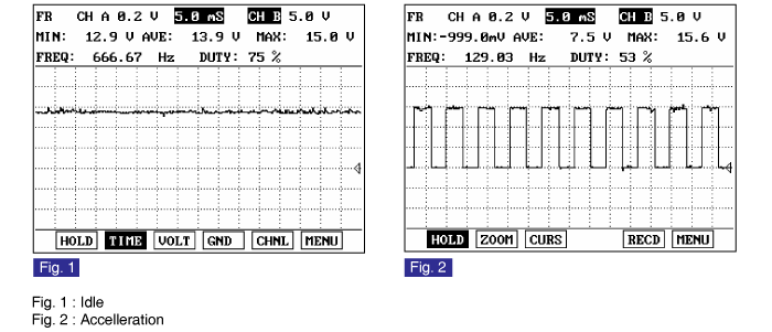
The oil control valve is commanded by a pulse-width-modulated signal from the engine control unit. A duty cycle of zero commands the cam phaser to its default position. A duty cycle of 100% commands the phaser to its maximum phased position. When the phaser must be controlled to an intermediate position, the duty cycle is maintained in the region of the ‘hold position’. This is a medium duty cycle, usually between 35% and 65%, depending on temperature and voltage conditions.
Resistance (Ω) | 6.7 ~ 7.7 |
IG "OFF" & connect scantool.
ENG "ON" and warm -up the engine to normal operating temperature.
Monitor "Cam Duty2, Cam Desired Position(B2) and Cam Actual Position(B2)" on the service data.
Are the "CAM" data displayed correctly ?

▶ Fault is intermittent caused by poor contact in the sensor’s and/or PCM’s connector or was repaired and PCM memory was not cleared. Thoroughly check connectors for looseness, poor connection, ending, corrosion, contamination, deterioration, or damage. Repair or replace as necessary and go to "Verification of Vehicle Repair" procedure

▶ Go to "Terminal and Connector Inspection" procedure
Many malfunctions in the electrical system are caused by poor harness and terminals. Faults can also be caused by interference from other electrical systems, and mechanical or chemical damage.
Thoroughly check connectors for looseness, poor connection, bending, corrosion, contamination, deterioration, or damage.
Has a problem been found?
▶ Repair as necessary and go to "Verification of Vehicle Repair" procedure
▶ Go to " Power Circuit Inspection " procedure.
IG "OFF" & Disconnect OCV(B2) connector.
IG "ON" & ENG "OFF".
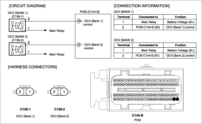
Measure voltage between terminal 1 of OCV(B2) harness connector and chassis ground.
Specification : B+
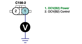
Is the measured voltage within specification ?
▶ Go to "Control Circuit Inspection " procedure.
▶ Check fuse between Main Relay and OCV is open or not installed.
▶ Check open in power circuit between Main Relay and OCV power circuit.
▶ Repair or repalce as necessary and then go to "Verification of Vehicle Repair" procedure.
Check short to ground in harness
IG "OFF" and disconnect OCV connector.
IG "ON" & ENG "OFF".
Measure resistance between terminal 2 of OCV harness connector and chassis ground.
Specification : Infinite
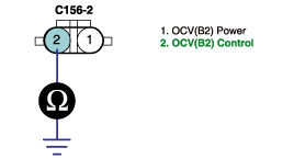
Is the measured resistance within specification ?
▶ Go to "Check open in harness" as follows
▶ Repair or replace as necessary and go to "Verification of Vehicle Repair" procedure.
Check open in harness
IG "OFF" and disconnect OCV and PCM connector.
Measure resistance between terminal 2 of OCV harness connector and terminal 61 of PCM harness connector.
Specification : Approx. below 1Ω
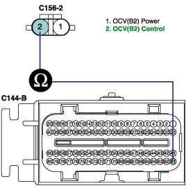
Is the measured resistance within specification ?
▶ Go to "Component Inspection" procedure.
▶ Repair or replace as necessary and then go to " Verification of Vehicle Repair" procedure.
Check OCV
IG "OFF" and disconnect OCV connector.
Measure resistance between terminal 1 and 2 of OCV. (Component Side)
Resistance (Ω) | 6.7 ~ 7.7 |
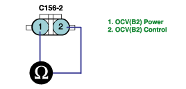
Is the measured resistance within specification ?
▶ Go to "OCV Actuation Test" as follows.
▶ Substitute with a known - good OCV and check for proper operation. If the problem is corrected, replace OCV and go to "Verification of Vehicle Repair" procedure.
OCV Actuation Test
Connect scantool and IG "ON"
Select "OCV" on the Actuation Test
Activate "OCV" by pressing "STRT(F1)" key
(should hear a faint click from Oil Control solenoid Valve)
Repeat this procedure 4 or 5 times to ensure reliability
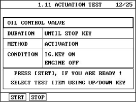
Does OCV generate click sound during acutation test ?
▶ Substitute with a known - good PCM and check for proper operation. If the problem is corrected, replace PCM and go to "Verification of Vehicle Repair" procedure.
There is a memory reset function on scantool that can erase optional parts automatically detected and memorized by PCM. Before or after testing PCM on the vehicle, use this function to reuse the PCM on the others
▶ Substitute with a known - good OCV and check for proper operation. If the problem is corrected, replace OCV and go to "Verification of Vehicle Repair" procedure.
After a repair, it is essential to verify that the fault has been corrected.
Monitor and record the Freeze Frame Data for the Diagnostic Trouble Code(DTC) which has been diagnosed.
Using a Scantool, Clear the DTCs
Operate the vehicle within conditions noted in the freeze frame data or enable conditions
Monitor that all rediness test have been verified as " Complete "
Are any DTCs present ?
▶ Go to the applicable troubleshoooting procedure.
▶ System is performing to specification at this time.
