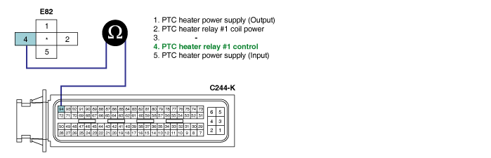
COMPONENT LOCATION
GENERAL DESCRIPTION

Because thermal efficiency of electronically controlled diesel engine is higher than that of gasoline engine, heat loss to cylinder wall is lower. This enables electronically controlled diesel engine to generate high power and have high fuel efficiency. However in other point of view, due to low engine coolant temperature, heating efficiency lowered then, driver is unsatisfied with the heating. To cope with this situation, PTC heater is installed in coolant line and it raises heating efficiency and raise coolant temperature.

※ Heater relay operating condition : When all the following condition are met.Blower ON, Engine speed below 700RPM, Battery voltage above 12.5V, Aircon OFF, Air temperature below 5℃, engine coolant temperature below 70℃ - Maximum operating duration is limited to 40 min.

DTC DESCRIPTION

P1634 is set when excessive current or "0"A is detected in heater relay control circuit for more than 1.0 sec. at heater relay operating condition. This code is due to 1)open or 2)short to battery or ground in heater relay control circuit or 3)component problem.

DTC DETECTING CONDITION

Item

Detecting Condition

Possible Cause

DTC Strategy

Voltage monitoring

PTC heater relay #1control circuit

Heater relay component

Enable Conditions

IG KEY "ON" (monitoring only performed at relay operating condition)

Threshold Value

Short to Battery

short to GND, wiring open

Diagnostic Time

1.0 sec.

Fail Safe

Fuel cut

NO

EGR Off

NO

Fuel Limit

NO

Check Lamp

NO

SPECIFICATION

Heater relay coil resistance

PTC heater operating temperature

PTC heater operating condition

52±5Ω (20℃)

Refer to "General Information"

Refer to "General Information"

SCHEMATIC DIAGRAM
MONITOR SCANTOOL DATA
1.

Connect Scantool to Data Link Connector (DLC).

2.

ENGINE "ON".(Engine coolant temp. below 70℃,Intake air temp. below 5℃)

3.

Blower switch "ON".

4.

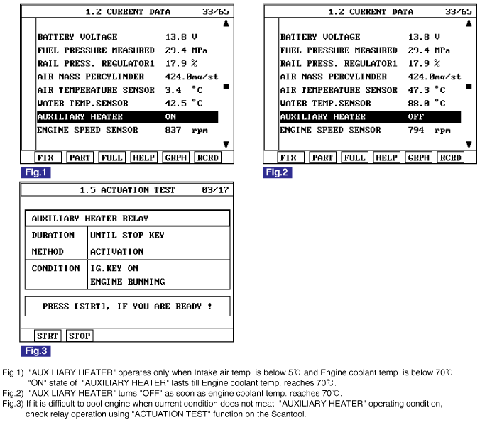
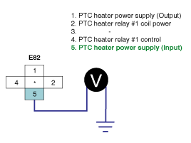
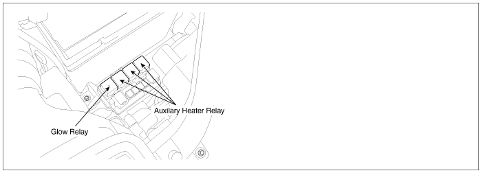
Monitor "AUXILIARY HEATER" parameter on the Scantool.

( As soon as turning engine ON "AUXILIARY HEATER" parameter turns "ON". Check if the parameter turns "OFF" after engine is warmed up.)

specification : Engine coolant temp. below 70℃(Intake air temp. below 5℃) : "AUXILIARY HEATER" "ON"

Engine coolant temp. above 70℃ : "AUXILIARY HEATER" "OFF"

TERMINAL AND CONNECTOR INSPECTION
1.

Electrical systems consist of a lot of harness and connectors, poor connection of terminals can cause various problems and damge of component.

2.

Perform checking procedure as follows.

(1)

Check damage of harness and terminals : Check terminals for contact resistance, corrosion and deformation.

(2)

Check connecting condition of ECM and component connector : Check terminal seperation, damage of locking device and connecting condition between terminal and wiring.

note

Disconnect the pin which requires checking at male connector and insert it to the terminal at female connector for checking connecting condition. ( after checking, reconnect the pin at correct position. )

3.

Is the problem found?

▶ Repair the trouble causing part and go to "Verification of Vehicle Repair".

▶ Go to "Power Circuit Inspection".

POWER CIRCUIT INSPECTION
1.

Check HOT AT ALL TIMES power circuit voltage

(1)

IG KEY "OFF", ENGINE "OFF"

(2)

Disconnect PTC heater relay #1.

(3)

Measure the voltage of PTC heater relay #1 connector terminal 5.

Specification : 11.5V~13.0V

(4)

Is the measured voltage within the specification?

▶ Go to "2. Check IG KEY "ON" power circuit voltage" as follows.

▶ Repair FUSIBLE LINK BOX 50A PTR HTR #1 FUSIBLE LINK and related circuit and go to "Verification of Vehicle Repair".

2.

Check IG KEY "ON" power circuit voltage

(1)

IG KEY "OFF", ENGINE "OFF"

(2)

Disconnect PTC heater relay #1.

(3)

IG KEY "ON"

(4)

Measure the voltage of PTC heater relay #1 connector terminal 2.

Specification : 11.5V~13.0V

(5)

Is the measured voltage within the specification?

▶ Go to "Control Circuit Inspection".

▶ Repair E/R JUNCTION BOX 15A SNSR2 FUSE and related circuit and go to "Verification of Vehicle Repair".

CONTROL CIRCUIT INSPECTION
1.

Check control circuit monitoring voltage

(1)

IG KEY "ON", ENGINE "OFF".

(2)

Disconnect PTC heater relay #1.

(3)

IG KEY "ON"

(4)

Measure the voltage of PTC heater relay #1connector terminal 4.

Specification : 8.0V~10.0V

(5)

Is the measured voltage within the specification?

▶ Go to "Component Inspection" .

▶ When voltage is not detected : Go to "2. Check open in control circuit" as follows.

▶ When high voltage is detected : Repair short to battery and go to "Verification of Vehicle Repair".

2.

Check open in control circuit

(1)

IG KEY "OFF", ENGINE "OFF"

(2)

Disconnect PTC heater relay #1 and ECM connector.

(3)

Check continuity between PTC heater relay #1 connector terminal 2 and ECM connector(C244-K) terminal 94.

specification : Continuity ( below 1.0Ω )

(4)

Is the measured resistance within the specification?

▶ Repair short to ground in controll circuit and go to "Verification of Vehicle Repair".

▶ Repair open in controll circuit and go to "Verification of Vehicle Repair".

COMPONENT INSPECTION
1.

Check PTC heater relay #1 component coil resistance

(1)

IG KEY "OFF", ENGINE "OFF".

(2)

Disconnect PTC heater relay #1.

(3)

Measure the resistance of PTC heater relay #1 component coil.

Specification : 52±5 Ω (20℃)

(4)

Is the measured resistance within the specification?

▶ Go to "2. Check PTC heater relay #1 component operation" as follows.

▶ Replace PTC heater relay #1 and go to "Verification of Vehicle Repair".

2.

Check PTC heater relay #1 component operation

(1)

IG KEY "OFF", ENGINE "OFF"

(2)

Disconnect PTC heater relay #1.

(3)

Supplies random B+ and ground to coil sides of PTC heater relay #1. ( terminal 85, 86)

(4)

Check continuity between PTC heater relay #1 terminal 30 and terminal 87.

specification : When power is supplied : Continuity ( below 1.0Ω )

When power is not supplied : Discontinuity ( Infinite Ω )

(5)

Is the measured resistance within the specification?

▶ Go to "Verification of Vehicle Repair".

▶ Replace PTC heater relay #1 and go to "Verification of Vehicle Repair".

※ Repeat this process 2~3 times.

VERIFICATION OF VEHICLE REPAIR

After a repair, it is essential to verify that the fault is corrected.

1.

After connecting Scantool select "DIAGNOSTIC TROUBLE CODES(DTCs)" mode.

2.

Clear recorded DTC using Scantool.

3.

Drive the vehicle within DTC "Enable conditions" in "General information".

4.

After selecting "DIAGNOSTIC TROUBLE CODES(DTCs)" mode and check if DTC is recorded again.

5.

Are any DTCs recorded ?

▶ Go to the DTC guide of recorded NO. in Scantool.

▶ System operates within specification.

Яндекс.Метрика