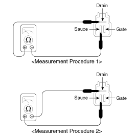
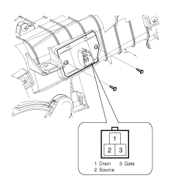
Remove the power mosfet. Measure drain-to-sauce resistance of the power mosfet.

Resistance (Drain-Sauce) | Subject | ||
1 | 2 | ||
Power mosfet | Drain | + | ― |
Sauce | ― | + | |
Section | Normal | ∞ | Approx 3M Ω |
Short | Approx 0 ~ 300 Ω | Approx 0 ~ 300 Ω | |
Open | ∞ | ∞ | |
Disconnect the negative (-) battery terminal.
Remove the power mosfet. Measure drain-to-sauce resistance of the power mosfet.

Resistance (Drain-Sauce) | Subject | ||
1 | 2 | ||
Power mosfet | Drain | + | ― |
Sauce | ― | + | |
Section | Normal | ∞ | Approx 3M Ω |
Short | Approx 0 ~ 300 Ω | Approx 0 ~ 300 Ω | |
Open | ∞ | ∞ | |
If the measured resistance is not specification, replace the power mpsfet.
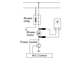
If measured resistance is specification, install power mosfet and ignition switch ON. Measure the voltage between blower motor terminals by operating control switch manually.
Select the control switch to raise voltage until high speed.

Fan | Motor Voltage |
Manual | |
First speed | 3.8 ± 0.5V |
Second speed | 5.0 ± 0.5V |
Third speed | 6.2 ± 0.5V |
Fourth speed | 7.4 ± 0.5V |
Fifth speed | 8.6 ± 0.5V |
Sixth speed | 9.8 ± 0.5V |
Seventh speed | 11.0 ± 0.5V |
eighth speed | Battery(+) |
If the measured voltage is not specification, substitute with a known-good power mosfet and check for proper operation.
If the problem is corrected, replace the power mosfet.
Disconnect the negative (-) battery terminal.
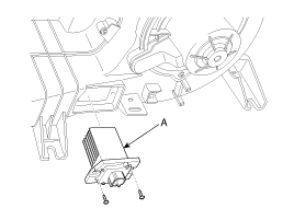
Disconnect the power mosfet connector (A) at the connecting part between heater and blower unit.

Remove the power mosfet (B) after loosening the mounting screws.

Installation is the reverse order of removal.