Monitor "HO2S(B1/S2)" item on the service data.
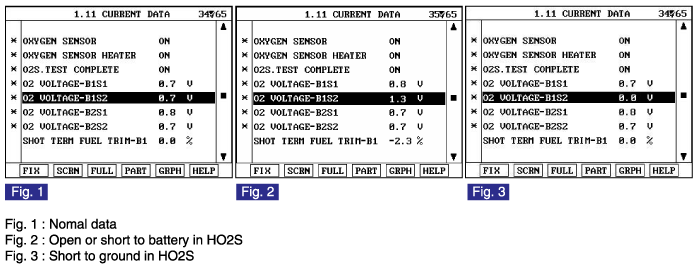
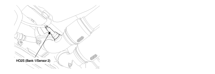
HO2S(B1/S2) is in the back of Catalytic Converter to check the proper operation of catalyst. As Exhaust gas already passed through catalyst, oxygen density in it is within specific range. If the oxygen density changes in accordance with HO2S(B1/S1), it means the poor performance of catalytic converter.
Checking output signals from HO2S every 10 sec. under detecting condition, if an output signal indicating open in the circuit lasts for more than 6.3 sec., PCM sets P0140. MIL(Malfunction Indication Lamp) turns on when the malfunction lasts till consecutive 2 driving cycle.
Item | Detecting Condition | Possible cause | |||||
DTC Strategy | ● Open | ● Poor Connection ● Open in harness ● HO2S(B1/S2) ● PCM | |||||
Enable Conditions | ● No sensor cooled status ● The minimum airflow ≥ 2g/s ● The battery voltage ≥ 10V ● Engine running state 〉60 sec. ● Coolant temperature ≥ 60℃(140℉) ● No fuel reduction ● No transient condition ● No fuel-cut state ● No disabling fault | ||||||
Threshold value | Case 1 | ● At pumping current ON ● 1.2V ≤ Voltage of HO2S ≤ 3.9V | |||||
Case 2 | ● At pumping current OFF ● 0.415V ≤ Voltage of HO2S ≤ 0.515V | ||||||
Diagnosis Time | ● Continuous (more than 6.3 sec.failure for every 10 sec.test) | ||||||
MIL On Condition | ● 2 driving cycles | ||||||
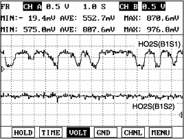
The amplitude of the signal output of the rear HO2S is small compared to the front HO2S because the rear HO2S detects emission gas purified by the catalytic converter. This is the normal signal waveform of the rear HO2S at idle.
Air/fuel mixture | Voltage(V) | ||
Rich | 0.75 ~ 1V | ||
Lean | 0 ~ 0.12V |
IG "OFF" & connect scantool.
ENG "ON" and warm -up the engine to normal operating temperature.
Monitor "HO2S(B1/S2)" item on the service data.

Is the service data displayed correctly ?

▶ Fault is intermittent caused by poor contact in the sensor’s and/or PCM’s connector or was repaired and PCM memory was not cleared. Thoroughly check connectors for looseness, poor connection, ending, corrosion, contamination, deterioration, or damage. Repair or replace as necessary and go to "Verification of Vehicle Repair" procedure

▶ Go to "Terminal and connector inspection" procedure
Many malfunctions in the electrical system are caused by poor harness and terminals.
Faults can also be caused by interference from other electrical systems, and mechanical or chemical damage.
Thoroughly check connectors for looseness, poor connection, bending, corrosion, contamination, deterioration, or damage.
Has a problem been found?

▶ Repair as necessary and go to "Verification of Vehicle Repair" procedure

▶ Go to " Signal Circuit Inspection " procedure.
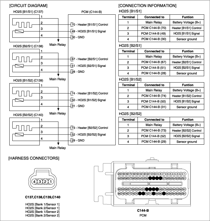
IG "OFF" and disconnect HO2S(B1/S2) connector.
IG "ON" and ENG "OFF"
Measure voltage between terminal 3 of HO2S(B1/S2) harness connector and chassis ground.
Specification : Approx. 3.5V - when pumping current is ON
Approx. 0.45V - when pumping current is OFF
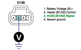
Is the measured voltage within specification?

▶ Go to "Ground Circuit Inspection" procedure.

▶ Repair open in harness, and go to "Verification of Vehicle Repair" procedure.
IG "ON" and disconnect HO2S(B1/S2) connector.
Measure voltage between terminal 3 of HO2S(B1/S2) harness connector and chassis ground.
Measure voltage between terminals 3 and 4 of HO2S(B1/S2) harness connector.
Specification : Voltage difference between measurement "A" and "B" is below 200mV.

Is the measured voltage within specification?

▶ Go to "Component inspection" procedure.

▶ Repair open or contact resistance in harness, and go to "Verification of Vehicle Repair" prcedure.
Visual Inspection of HO2S
Visually/physically inspect following items:
Inspect the Rear HO2S for Contaminated, deteriorated or aged Rear HO2S
If contamination is evident on the HO2S, replace contaminated sensor
Is the HO2S(B1/S2) normal?

▶ Substitute with a known - good PCM and check for proper operation. If the problem is corrected, replace PCM and go to "Verification of Vehicle Repair" procedure.

▶ Substitute with a known - good HO2S(B1/S2) and check for proper operation. If the problem is corrected, replace HO2S(B1/S2) and go to "Verification of Vehicle Repair" procedure.
There is a memory reset function on scantool that can erase optional parts automatically detected and memorized by PCM. Before or after testing PCM on the vehicle, use this function to reuse the PCM on the others
After a repair, it is essential to verify that the fault has been corrected.
Monitor and record the Freeze Frame Data for the Diagnostic Trouble Code(DTC) which has been diagnosed.
Using a Scantool, Clear the DTCs
Operate the vehicle within conditions noted in the freeze frame data or enable conditions
Monitor that all rediness test have been verified as " Complete "
Are any DTCs present ?

▶ Go to the applicable troubleshoooting procedure.

▶ System is performing to specification at this time.