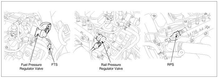
COMPONENT LOCATION
GENERAL DESCRIPTION

As inputted rail pressure sensor signal, ECM of Commom rail diesel engine controls fuel metering unit(MPROP-intergrated with high press. pump) and rail pressure control valve(PCV-integrated with common rail) in order to maintain optimum rail pressure according to current engine rpm and load. However when the problem that leads rail pressure to out of target value intended by ECM occurs due to mechanical or electronical reason, ECM limits engine performance and sets DTC by limiting fuel (stops injector operation) in order to prevent engine from being controlled abnormally. "rail pressure monitoring error" is the DTC which diagnose 1).supplying state of low pressure fuel and 2).mechanical operating conditions of high pressure pump and 3). RPCV indirectly based on RPS output voltage and RPS duty. thus, repair relavant to this DTC requires mechanics the total understand of fuel system.

DTC DESCRIPTION

P1186 is set when measured rail pressure, within the range where rail pressure is controlled by MPROP, is higher or lower than 200bar controlled as target rail pressure or when high pump amount is lowered than limited minimum value for lasting 0.8sec.. Check whether less amount of fuel is delivered than target amount of fuel controlled by ECM, too much return amount delivered to common rail or stuck resulting from low voltage of rail pressure sensor.

DTC DETECTING CONDITION

Item

Detecting Condition

Possible Cause

DTC Strategy

Voltage monitoring

rail pressure regulator valve(close stuck)

rail pressure control valve(open stuck)

Rail pressure sensor(Output fixed at high voltage line)

Enable Conditions

Engine running

Threshold Value

Rail pressure is below target rail pressure by more than 200bar at fuel pressure regulator(MPROP) operating condition.

Diagnostic Time

0.8 sec.

Fail Safe

Fuel cut

NO

EGR Off

NO

Fuel Limit

YES

Check Lamp

YES

MONITOR SCANTOOL DATA
1.

Monitoring rail pressure data

(1)

Connect Scantool to Data Link Connector (DLC).

(2)

Warm engine up to normal operating temperature.

(3)

Turn "OFF" electrical devices and A/C.

(4)

Monitor "FUEL PRESSURE MEASURED", "FUEL PRESS. S/POINT", "RAIL PRESS. REGULATOR1", "INJ. PUMP REGULATOR" parameter on the Scantool.

Specification : FUEL PRESSURE MEASURED similar to "FUEL PRESSURE-TARGET"

FUEL PRESS. S/POINT : 28.5 ± 5 Mpa

RAIL PRESS. REGULATOR1 : 17 ± 5%

INJ. PUMP REGULATOR : 35 ± 5%
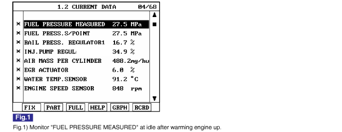
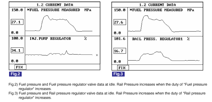
Check if "FUEL PRESSURE MEASURED"data is similar to "FUEL PRESS. S/POINT". Not only former two data but also "RAIL PRESS. REGULATOR1" and "INJ. PUMP REGULATOR"should be monitored carefully. Although "FUEL PRESSURE MEASURED" is similar to "FUEL PRESS. S/POINT", if "RAIL PRESS. REGULATOR1" and "INJ. PUMP REGULATOR" is out of specification, it means wear, leakage, stuck of fuel system.
2.

Monitoring rail pressure data at acceleration(loading condition).

(1)

Connect Scantool to Data Link Connector (DLC).

(2)

Warm engine up to normal operating temperature.

(3)

Turn "OFF" electrical devices and A/C.

(4)

Monitor "FUEL PRESSURE MEASURED", "INJ. PUMP REGULATOR","RAIL PRESS. REGULATOR1" parameter on the Scantool.

Specification :

Idle(without load)

Accelerating(stall test)

Diagnosis

FUEL PRESSURE MEASURED

28 ± 5 Mpa

above 75 Mpa

press. increases

INJ. PUMP REGULATOR

35 ± 5%

38 ± 5%

duty increases

RAIL PRESS. REGULATOR1

17 ± 5%

45 ± 5%

duty increases

note

The waveform of fuel pressure regulator valve installed at high pressure pump(fuel detecting MPROP) shows 35 ± 5% duty at idle, duty rises to approx. 40% at acceleration to raise rail pressure.

▶ Fuel amonut delivered from injection pump to rail is increases if the duty of "Fuel pressure regulator" increases

The waveform of rail pressure regulator valve installed at common rail shows 17 ± 5% duty at idle, duty rises to approx. 45% at acceleration to raise rail pressure.

▶ If the current increases, pressure in common rail will increase. because fuel return amount delivered to commom rail will decrease.

VERIFICATION OF VEHICLE REPAIR

After a repair, it is essential to verify that the fault is corrected.

1.

After connecting Scantool select "DIAGNOSTIC TROUBLE CODES(DTCs)" mode.

2.

Clear recorded DTC using Scantool.

3.

Drive the vehicle within DTC "Enable conditions" in "General information".

4.

After selecting "DIAGNOSTIC TROUBLE CODES(DTCs)" mode and check if DTC is recorded again.

5.

Are any DTCs recorded ?

▶ Go to the DTC guide of recorded NO. in Scantool.

▶ System operates within specification.

Яндекс.Метрика