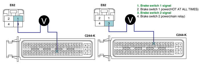
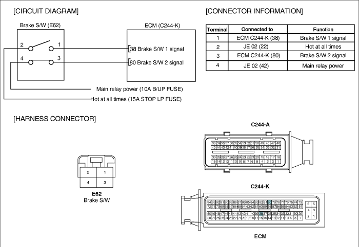
Brake switch is connected to brake pedal and transmits brake operating state to ECM.When the output signal of APS is higher than what driver intended during driving (e.g. short to high voltage line in APS circuit, false signal ), driver depresses brake pedal.Like this, if driver's decelerating intension is transmitted to ECM (break pedal depressed)when APS output voltage is high, ECM recognizes APS trouble and Limp Home mode is activated.At Limp Home mode, engine speed is fixed at approx. 1000RPM and engine power generation is limitted.Even at Limp home mode, if correct APS signal is detected, Limp Home mode is deactivated. Brake switch, which monitors proper operation of APS, is devided 1 and 2 for the fidelity of brake switch.
When brake switch operates correctly, switch 1 is OFF and switch 2 is ON when releasing brake pedal, while switch 1 is ON and switch 2 is OFF when depressing brake pedal. thus when the signal from a switch is different from the other's, brake switch is in good condition. When the signal from a switch is same as the other's, brake switch is fault.
Item | Detecting Condition | Possible Cause | ||
DTC Strategy | ● Signal monitoring | ● Brake switch component ● Abnormal brake pedal height ● Brake switch circuit | ||
Enable Conditions | ● IG KEY "ON" | |||
Threshold Value | ● Wiring open or short | |||
Diagnostic Time | ● 180 sec. | |||
Fail Safe | Fuel cut | NO | ||
EGR Off | NO | |||
Fuel Limit | NO | |||
Check Lamp | NO |
Condition | Brake Pedal Released | Brake Pedal Depressed | ||
switch state | Switch 1 | Switch 2 | Switch 1 | Switch 2 |
Opened | Closed | Closed | Opened |
Connect Scantool to Data Link Connector (DLC).
Warm engine up to normal operating temperature.
Turn "OFF" electrical devices and A/C.
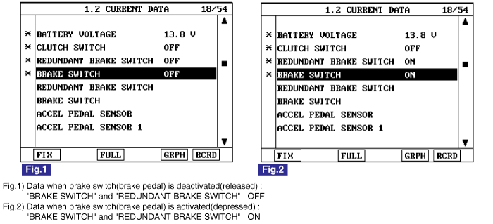
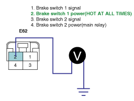
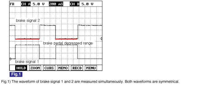
Monitor "BRAKE SWITCH" and "REDUNDANT BRAKE SWITCH" parameter on the Scantool.
specification : When brake pedal is released : "BRAKE SWITCH" and "REDUNDANT BRAKE SWITCH" : OFF
When brake pedal is depressed : "BRAKE SWITCH" and "REDUNDANT BRAKE SWITCH" : ON
Electrical systems consist of a lot of harness and connectors, poor connection of terminals can cause various problems and damge of component.
Perform checking procedure as follows.
Check damage of harness and terminals : Check terminals for contact resistance, corrosion and deformation.
Check connecting condition of ECM and component connector : Check terminal seperation, damage of locking device and connecting condition between terminal and wiring.
Disconnect the pin which requires checking at male connector and insert it to the terminal at female connector for checking connecting condition. ( after checking, reconnect the pin at correct position. )
Is the problem found?
▶ Repair the trouble causing part and go to "Verification of Vehicle Repair".
▶ Go to "Power Circuit Inspection".
Check brake switch 1 "HOT AT ALL TIMES"
IG KEY "OFF", ENGINE "OFF".
Disconnect brake switch connector.
Measure the voltage of terminal 2 of brake switch connector.
Specification : 11.5V~13.0V
Is the measured voltage within the specification?
▶ Go to "2.Check brake switch 2 main relay power" as follows.
▶ Repair I/P JUNCTION BOX 15A STOP FUSE and related circuit and go to "Verification of Vehicle Repair".
Check brake switch 2 main relay power
IG KEY "OFF", ENGINE "OFF".
Disconnect brake switch connector.
IG KEY "ON".
Measure the voltage of brake switch connector terminal 4.
Specification : 11.5V~13.0V
Is the measured voltage within the specification?
▶ Go to "Signal Circuit Inspection".
▶ Repair E/R JUNCTION BOX 15A SNSR1 FUSE and related circuit and go to "Verification of Vehicle Repair".
Check brake switch signal circuit voltage
IG KEY "OFF", ENGINE "OFF".
Disconnect ECM connector with brake switch connector connected.
Disconnect E/R JUNCTION BOX main relay, connect main relay terminal 30 and 87, 87a using jump wire.
Measure the voltage of ECM connector (C244-K) terminal 38 and 80 as depressing brake pedal.
Brake Pedal Released | Brake Pedal Depressed | |
Brake switch 1 (terminal 38) | 0.0V~0.1V | 11.5V~13.0V |
Brake switch 2 (terminal 80) | 11.5V~13.0V | 0.0V~0.1V |
Is the measured voltage within the specification?
▶ Go to "2. Check open in signal circuit".
▶ If there is any problem on component after checking "Component Inspection" procedure, go to "2. Check open in signal circuit " procedure.
Check open in signal circuit
IG KEY "OFF", ENGINE "OFF".
Disconnect brake switch connector and ECM connector.
Check continuity between brake switch connector terminal 1 and ECM connector(C244-K) terminal 38. (brake switch 1 circuit)
Check continuity between brake switch connector terminal 3 and ECM connector(C244-K) terminal 80. (brake switch 2 circuit)
specification : Continuity ( below 1.0Ω )
Is the measured resistance within the specification?
▶ Repair short in signal circuit and go to "Verification of Vehicle Repair".
▶ Repair open in signal circuit and go to "Verification of Vehicle Repair".
IG KEY "OFF", ENGINE "OFF".
Disconnect brake switch connector.
Check continuity between brake switch component terminal 1and 2 as depressing brake pedal. (brake switch 1)
Check continuity between brake switch component terminal 3and 4 as depressing brake pedal. (brake switch 2)
Brake Pedal Released | Brake Pedal Depressed | ||
Switch 1 | Switch 2 | Switch 1 | Switch 2 |
Discontinuity | Continuity | Continuity | Discontinuity |
Does brake switch operate correctly?
▶ Go to "Verification of Vehicle Repair".
▶ Unless any problem is detected after checking height of brake pedal, replace brake switch component and go to "Verification of Vehicle Repair".
After a repair, it is essential to verify that the fault is corrected.
After connecting Scantool select "DIAGNOSTIC TROUBLE CODES(DTCs)" mode.
Clear recorded DTC using Scantool.
Drive the vehicle within DTC "Enable conditions" in "General information".
After selecting "DIAGNOSTIC TROUBLE CODES(DTCs)" mode and check if DTC is recorded again.
Are any DTCs recorded ?
▶ Go to the DTC guide of recorded NO. in Scantool.
▶ System operates within specification.