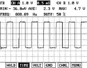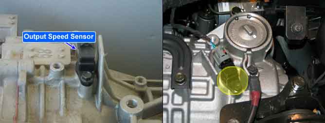
The Output Speed Sensor outputs pulse-signals according to the revolutions of the output shaft of the transmission. The Output Speed Sensor is installed in front of the Transfer Drive Gear to determine the Transfer Drive Gear rpms by counting the frequency of the pulses. This value, together with the throttle position data, is mainly used to decide the optimum gear position.
The TCM sets this code if the calculated value of the pulse-signal is noticeably different from the value calculated, using the Vehicle Speed Sensor output, when the vehicle is running faster than 19 Mile/h(30 km/h). The TCM will initiate the fail safe function if this code is detected.
Item | Detecting Condition | Possible Cause |
DTC Strategy | ● Speed rationality check | ● Signal circuit is open or short. ● Sensor power circuit is open ● Sensor ground circuit is open ● Faulty OUTPUT SPEED SENSOR ● Faulty PCM |
Enable Conditions | ● Vehicle speed is over 19 Mile/h(30 Km/h) ● Ne≥1000rpm (only at 1st or 2nd gear ) ● 11V ≤ Battery Voltage ≤ 16V ● TM oil temperature ≥ -23℃ | |
Threshold Value | ● Vehicle speed caliculated from output speed ≤ 50%(the vehicle speed from vehicle speed sensor) | |
Diagnostic Time | ● More than 1sec | |
Fail Safe | ● Locked into 3rd or 2nd gear. ● Apply an electric current to Solenoide valve ● Manual shifting is possibe(2nd → 3rd, 3rd → 2nd) |
Input shaft & Output shaft speed sensor
● Type : Hall sensor
● Current consumption : 22mA(MAX)
● Sensor body and sensor connector have been unified as one.