1.
Power circuit inspection
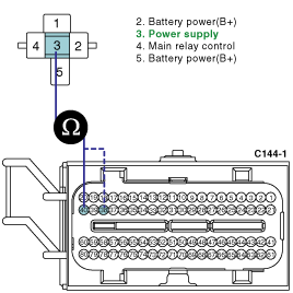
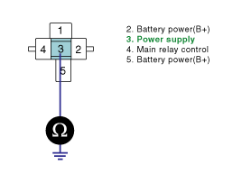
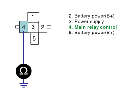
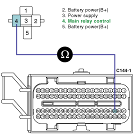
(1)
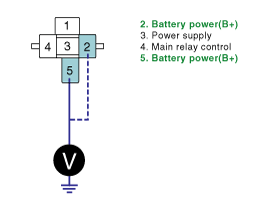
Key "OFF".
(2)
Disconnect the main relay connector.
(3)
Key "ON".
(4)
Measure the voltage between terminal 2 of main relay harness connector and chassis ground.
(5)
Measure the voltage between terminal 5 of main relay harness connector and chassis ground.
Specification : B+
(6)
Is the measured voltage within specification ?
YES
▶ Go to "Check open in harness" procedure.
NO
▶ Check the fuse between battery and main relay.
▶ Repair Open or Short to ground in power circuit and go to "Verification of Vehicle Repair" procedure