Is the problem found?

▶ Repair the trouble causing part and go to "Verification of Vehicle Repair".

▶ Go to "Power Circuit Inspection".
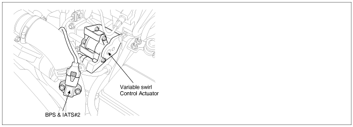
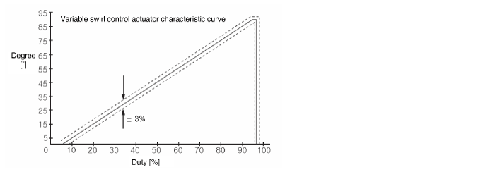
Variable swirl control actuator consists of DC motor and motor position sensor(potentiometer) which detects the position of swirl valve.As closing one intake port out of two at idle and below 3000RPM, swirl effect is taken on intake air. This swirl effect increases air flow rate.
However, because air flow rate is too high, swirl effect is neglectable thus, swirl valve is opened for efficiency of intake air.
To prevent swirl valve and shaft form being stuck by foreign metarial, and to learn max opening and closing position of swirl valve, it is fully opened and closed twice at turning engine OFF.
※Swirl
The air flow which indicates Intake air swirls with respect to the axis passing through the centre of piston with length-direction by intake port which is eccentric from the centre of combustion chamber.
P2016 is set when variable swirl valve position sensor output voltage below 0.18V is detected for more than 2.5 sec. This code is due to open in power circuit or short to ground in signal circuit.
Item | Detecting Condition | Possible Cause | ||
DTC Strategy | ● Voltage monitoring | ● Variable swirl valve position sensor circuit ● Variable swirl valve position sensor component | ||
Enable Conditions | ● IG KEY "ON" | |||
Threshold Value | ● Output voltage below minimum value( below 180mV ) | |||
Diagnostic Time | ● 2500ms | |||
Fail Safe | Fuel cut | NO | ||
EGR Off | NO | |||
Fuel Limit | NO | |||
Check Lamp | NO | |||
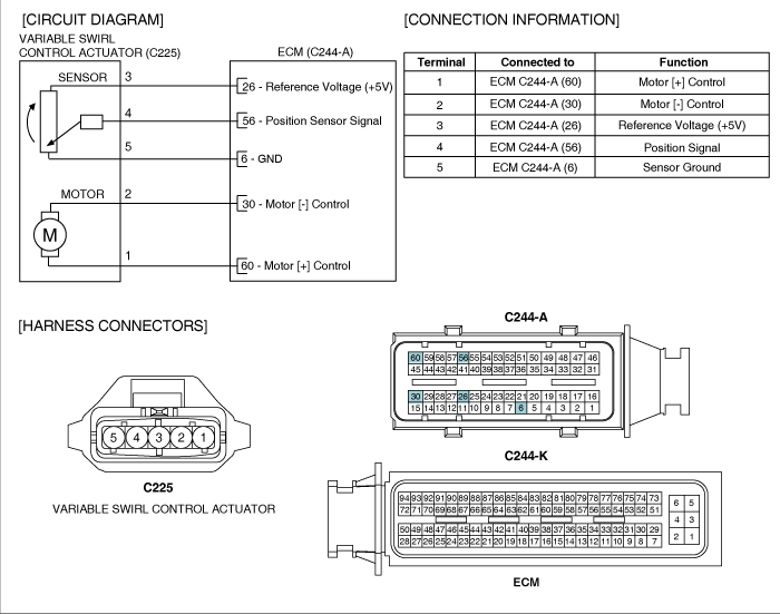
Electrical systems consist of a lot of harness and connectors, poor connection of terminals can cause various problems and damge of component.
Perform checking procedure as follows.
Check damage of harness and terminals : Check terminals for contact resistance, corrosion and deformation.
Check connecting condition of ECM and component connector : Check terminal seperation, damage of locking device and connecting condition between terminal and wiring.
Disconnect the pin which requires checking at male connector and insert it to the terminal at female connector for checking connecting condition. ( after checking, reconnect the pin at correct position. )
Is the problem found?

▶ Repair the trouble causing part and go to "Verification of Vehicle Repair".

▶ Go to "Power Circuit Inspection".
Check power circuit voltage
IG KEY "OFF", ENGINE "OFF"
Disconnect variable swirl control actuator connector.
IG KEY "ON"
Measure the voltage of variable swirl control actuator connector terminal 3.
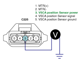
Specification : 4.8V~5.1V
Is the measured voltage within the specification?

▶ Go to "Signal Circuit Inspection".

▶ Repair open in power circuit and go to "Verification of Vehicle Repair".
Check signal circuit voltage
IG KEY "OFF", ENGINE "OFF"
Disconnect variable swirl control actuator connector.
IG KEY "ON"
Measure the voltage of variable swirl control actuator connector terminal 4.
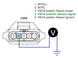
Specification : 4.8V~5.1V
Is the measured voltage within the specification?

▶ Go to "Component Inspection".

▶ Go to "2. Check short to ground in signal circuit" as follows.
Check short to ground in signal circuit
IG KEY "OFF", ENGINE "OFF"
Disconnect variable swirl control actuator connector and ECM connector.
Check continuity between variable swirl control actuator connector terminal 4 and chassis ground.

Specification : Discontinuity(Infinite Ω)
Is the measured resistance within the specificaiton?

▶ Go to "Component Inspection".

▶ Repair short to ground in signal circuit and go to "Verification of Vehicle Repair".
Check variable swirl control actuator position sensor resistance
IG KEY "OFF", ENGINE "OFF"
Disconnect variable swirl control actuator.
Measure the resistance of variable swirl control actuator component terminal 3,4,5 referring "Terminal resistance table" as follows.
Detecting terminal | Resistance ( KΩ 20℃ ) | Characteristic | Component connector shape | ||
valve fully opend | valve fully closed | ||||
variable swirl control actuator position sensor | 3(power)-5(ground) | 4.47±0.1KΩ | 4.47±0.1KΩ | stable | 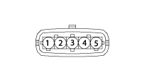 |
3(power)-4(signal) | 4.81±0.1KΩ | 0.85±0.1KΩ | resistance drops | ||
4(signal)-5(ground) | 0.75±0.1KΩ | 4.71±0.1KΩ | resistance rises | ||
Is the measured resistance within the specification?

▶ "2. Check variable swirl control actuator position sensor operation".

▶ Replace variable swirl control actuator assy' and go to "Verification of Vehicle Repair".
Check variable swirl control actuator position sensor operation
IG KEY "ON", ENGINE "ON".
Keep engine at idle state.
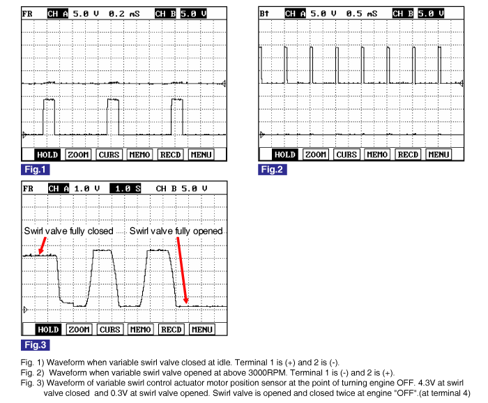
Monitor the waveform of variable swirl control actuator terminal 4 with oscilloscope.
Turning off engine, monitor the waveform of variable swirl control actuator at the point of operation stop.
Specification : Refer to Signal Waveform & Data "Fig.3)"
Does variable swirl control actuator and position sensor operations are OK?

▶ Go to "Verification of Vehicle Repair".

▶ Replace variable swirl control actuator assy' and go to "Verification of Vehicle Repair".
After a repair, it is essential to verify that the fault is corrected.
After connecting Scantool select "DIAGNOSTIC TROUBLE CODES(DTCs)" mode.
Clear recorded DTC using Scantool.
Drive the vehicle within DTC "Enable conditions" in "General information".
After selecting "DIAGNOSTIC TROUBLE CODES(DTCs)" mode and check if DTC is recorded again.
Are any DTCs recorded ?

▶ Go to the DTC guide of recorded NO. in Scantool.

▶ System operates within specification.