Monitor DTC related to "ETS or CAM" on scantool


Comparing actual torque and desired torque, PCM diagnoses calculated torque state. Actual torque keeps lower than desired torque, PCM checks if actual torque is higher than desired torque. deviding condition into two state, dynamic and steady states, PCM applies different diagnosis logic. Because the responses due to this code is similar to that of MAF control error, checking MAF at first.
If the difference between actual torque and desired torque is higher than the threshold value, PCM sets P161B and MIL(Malfunction Indication Lamp) turns on when the malfunction lasts till 1 driving cycle.
ITEM | Detecting Condition | Possible Cause | |
DTC Strategy | ● Determines if Delivered Torque Is Grossly Different fromDesired Torque | ● Intake air leakage ● Faulty ETS System ● Clogged exhaust system ● Faulty PCM | |
Enable Conditions | Case 1 | ● Engine Running state ● Engine Speed 〉 600rpm ● Desired Flywheel Torque Within 20Nm 〉1sec. | |
Case 2 | ● Pedal Position 〈 0.8% ● Torque Command Source = Accel pedal ● Engine Speed 〉desired torque engine speed ● All injectors enabled | ||
Threshold value | Case 1 | ● Actual net torque-desired torque 〉threshold | |
Case 2 | ● Normalized fuel flow 〉threshold | ||
Diagnosis Time | ● Continuous | ||
MIL On Condition | ● 1 Driving Cycle | ||
Conect scantool to DLC(Data Link Connector)
Warm-up the engine to normal operating temperature.
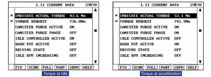
Monitor "Actual Torque & Torque Request" parameters on scantool
Monitor DTC related to "ETS or CAM" on scantool

Are there any DTC related to "ETS" or "CAM" on the scantool ?

▶ Repair "ETS" or "CAM" system first, then, go to "Terminal and Connector Inspection" procedure.

▶ Go to "Terminal and Connector Inspection" procedure.
Many malfunctions in the electrical system are caused by poor harness and terminals. Faults can also be caused by interference from other electrical systems, and mechanical or chemical damage.
Thoroughly check connectors for looseness, poor connection, bending, corrosion, contamination, deterioration, or damage.
Has a problem been found?

▶ Repair as necessary and go to "Verification of Vehicle Repair" procedure

▶ Go to " System Inspection " procedure.
Check air leakage
Check contamination or installation of Gasket
▶ Check throttle body gasket
▶ Check gasket between intake manifold and surge tank.
▶ Check contamination or clog by foreign material of gasket between intake manifold and injector.
▶ Check contamination or open stuck resulting from foreign material between surge tank and PCSV.
Is there any air leakage ?

▶ Repair or replace as necessary and then, go to "Verification of Vehicle Repair" procedure.

▶ Go to "Check exhaust system for clogging" as follows.
Check exhaust system for clogging
Check exhaust system.
▶ Clogged or broken muffler
▶ Broken catalyst
Is the exhaust system colgged ?

▶ Go to "Check throttle valve for stuck" as follows.

▶ Repair or repalce as necessary and then, go to "Verification of Vehicle Repair" procedure.
Check throttle valve for stuck
IG "OFF".
Remove air hose between throttle body and airflow sensor.
Check if throttle valve is sutck by foreign material.
Is the throttle valve normal ?

▶ Go to "Component Inspection" procedure.

▶ After getting rid of foreign material, check that throttle valve is normal and check for proper operation. If the problem is corrected,replace ETC and then go to "Verification of Vehicle Repair" procedure.
Erase the trouble codes on PCM
Turn the ignition key off and keep this condition until the main relay is turned off.(It will takes 10sec.)
Turn ignition key on more than 1second to record the throttle motor position on the EEPROM
Check resistance of ETS Motor
IG "OFF"
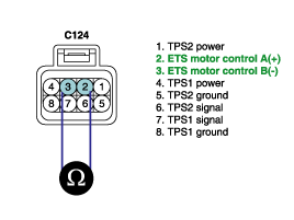
Disconnect ETS motor & TPS connector.
Measure resistance between terminal 2 and 3 of ETS motor & TPS connector.(Component Side)
Specification : Approx. 1.275 ~ 1.725Ω@ 23℃(73.4 °F)

Is the measured resistance within specifications ?

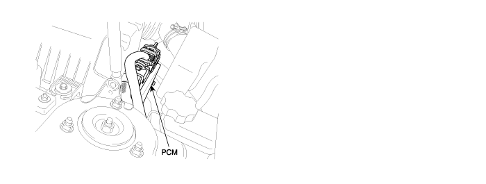
▶ Substitute with a known-good PCM and check for proper operation. If the problem is corrected,replace PCM and then go to "Verification of Vehicle Repair" procedure.
There is a memory reset function on scantool that can erase optional parts automaticallydetected and memorized by PCM.
Before or after testing PCM on the vehicle, use this function to reuse the PCM on the others

▶ Substitute with a known-good ETC and check for proper operation. If the problem is corrected,replace ETC and then go to "Verification of Vehicle Repair" procedure.
Erase the trouble codes on PCM
Turn the ignition key off and keep this condition until the main relay is turned off.(It will takes 10sec.)
Turn ignition key on more than 1second to record the throttle motor position on the EEPROM
After a repair, it is essential to verify that the fault has been corrected.
Monitor and record the Freeze Frame Data for the Diagnostic Trouble Code(DTC) which has been diagnosed.
Using a Scantool, Clear the DTCs
Operate the vehicle within conditions noted in the freeze frame data or enable conditions
Monitor that all rediness test have been verified as " Complete "
Are any DTCs present ?

▶ Go to the applicable troubleshoooting procedure.

▶ System is performing to specification at this time.