3.
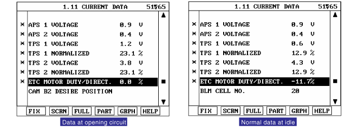
Monitor "ETS Motor" items on Current Data
ETC(Electronic Throttle Control Valve) is the device controlling amount of air to engine acccording to driver's intension. Different from the existing mechanical throttle valve which is composed of accelerator pecal and connecting wire cable, ETC consists of a motor, a throttle body and a throttle position sensor. Receiving input signals from electronic accelerator pedal module, PCM lets ETC motor control throttle valve. With ETC, cruise control system works without any additional device.
Checking output signals from TPS every 8.5 sec. under detecting condition, if the difference between real and target throttle position is above the specified value, PCM sets P0638. MIL(Malfunction Indicatin Lamp) turns on when the malfunction lasts till 1 driving cycle.
Item | Detecting Condition | Possible cause | |
DTC Strategy | ● ETS position control malfunction | ● Throttle stuck ● Open in motor circuit ● Faulty motor ● Faulty PCM | |
Enable Conditions | ● Engine works ● Battery voltage 〉5V | ||
Thresh old value | Case1 | ● l real ETS motor & TPS value - target ETS motor & TPS value l 〉4.5° | |
Case2 | ● When real Throttle position 〈36°, real throttle position - target throttle position 〈 - 4.5° | ||
Case3 | ● real throttle position - target throttle position 〈 - 18° | ||
Diagnosis Time | ● Continuous (More than 0.6 seconds failure for every 15.6 seconds test ) | ||
MIL On Condition | ● 1 driving cycle | ||
Throttle opening (°) | Output voltage (V) [Verf = 5.0V] | |
TPS1 | TPS2 | |
0° | 0.0V | 5.0V |
10° | 0.5V | 4.5V |
20° | 0.9V | 4.1V |
30° | 1.4V | 3.6V |
40° | 1.8V | 3.2V |
50° | 2.3V | 2.7V |
60° | 2.7V | 2.3V |
70° | 3.2V | 1.8V |
80° | 3.6V | 1.4V |
90° | 4.1V | 0.9V |
100° | 4.5V | 0.5V |
110° | 5.0V | 0.0V |
Ignition "OFF"
Connect Scantool and Engine "ON"
Monitor "ETS Motor" items on Current Data
Are those related current data displayed correctly ?

▶ Fault is intermittent caused by poor contact in Sensor’s and/or PCM’s connector or was repairedand PCM memory was not cleared. Thoroughly check connectors for looseness, poor connection,bending, corrosion, contamination, deterioration, or damage. Repair or replace as necessary and goto "Verification of Vehicle Repair" procedure

▶ Go to "Terminal and Connector Inspection" procedure.
Many malfunctions in the electrical system are caused by poor harness and terminals. Faults can also be caused by interference from other electrical systems, and mechanical or chemical damage.
Thoroughly check connectors for looseness, poor connection, bending, corrosion, contamination, deterioration, or damage.
Has a problem been found?
▶ Repair as necessary and go to "Verification of Vehicle Repair" procedure
▶ Go to " Control Circuit Inspection " procedure.
Check voltage
IG "OFF".
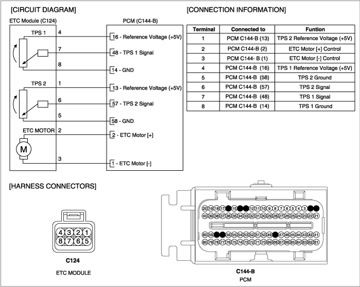
Disconnect ETS motor & TPS connector.
IG "ON" and ENG "OFF"
Measure the voltage between terminal 2,3 of ETS motor & TPS harness connector and chassis ground.
Specification : Approx. 12V
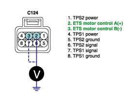
Is the measured voltage within specification?
▶ Go to "Component inspection" procedure.
▶ Go to "Check open in harness" as follows.
Open in control circuit inspection
IG "OFF"
Disconnect ETS motor & TPS connector and PCM connector.
Measure the resistance between terminal 2 of ETS motor & TPS harness connector and terminal 2 of PCM harness connector.
Measure the resistance between terminal 3 of ETS motor & TPS harness connector and terminal 1 of PCM harness connector.
Specification : Approx. below 1Ω
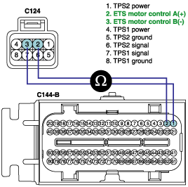
Is the measured resistance within specification ?
▶ Go to "Component inspection" procedure.
▶ Repair Open in motor harness and go to "Verification of Vehicle Repair" procedure.
Check throttle valve for stuck
IG "OFF".
Disconnect the air hose between throttle body and air mass flow sensor.
Check stuck on throttle valve.
Is the throttle valve normal?
▶ Go to check "ETS motor resistance" as follows.
▶ Repair or replace as necessary and go to "Verification of Vehicle Repair" procedure.
Check ETS motor resistance
IG "OFF".
Disconnect ETS motor & TPS connector.
Measure the resistance between terminal 2 and 3 of ETS motor & TPS connector(component side).
Specification : Approx. 1.275 ~ 1.725Ω @ 23℃ (73.4℉)
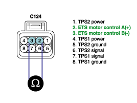
Is the measured resistance within specification?
▶ Go to "ETC motor actuation test" procedure.
▶ Substitute with a known - good ETC motor and check for proper operation. If the problem is corrected, replace ETC motor and go to "Verification of Vehicle Repair" procedure.
※ Procedure of ETS Initialization
1. Erase the trouble codes on PCM
2. Turn the ignition key off and keep this condition until the main relay is turned off.(It will takes 10 second)
3. Turn ignition key on more than 1second to record the throttle motor position on the EEPROM
ETC motor actuation test
IG "OFF".
Connect ETS motor & TPS connector.
After IG "ON", execute the "ETC motor actuation test" by Scantool.
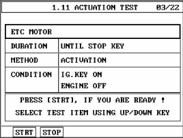
Does the "ETC motor actuation test" execute normally?
▶ Substitute with a known - good PCM and check for proper operation. If the problem is corrected, replace PCM and go to "Verification of Vehicle Repair" procedure.
▶ Substitute with a known - good ETC motor and check for proper operation. If the problem is corrected, replace ETC motor and go to "Verification of Vehicle Repair" procedure.
※ Procedure of ETS Initialization
1. Erase the trouble codes on PCM
2. Turn the ignition key off and keep this condition until the main relay is turned off.(It will takes 10 second)
3. Turn ignition key on more than 1second to record the throttle motor position on the EEPROM
After a repair, it is essential to verify that the fault has been corrected.
Monitor and record the Freeze Frame Data for the Diagnostic Trouble Code(DTC) which has been diagnosed.
Using a Scantool, Clear the DTCs
Operate the vehicle within conditions noted in the freeze frame data or enable conditions
Monitor that all rediness test have been verified as " Complete "
Are any DTCs present ?
▶ Go to the applicable troubleshoooting procedure.
▶ System is performing to specification at this time.
