4.
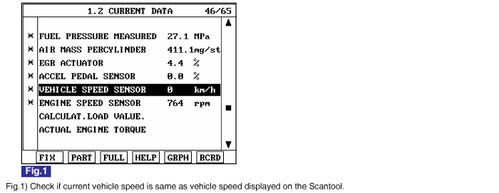
Monitor "VEHICLE SPEED SENSOR " parameter on the Scantool.
specification : current vehicle speed is displayed.
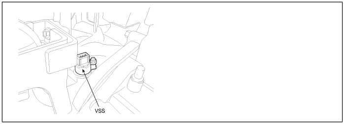
Vehicle Speed Sensor(VSS) is hall sensor type and senses the rotating speed of differential gear mounted on transaxle.Comparing engine speed with vehicle speed calculated based on vehicle speed sensor signal, ECM recognizes engaged gear. And based on the information about engaged gear, ECM performs optimum fuel injection quantity correction. VSS signal is also used in speed meter of cluster, ETACS(or BCM), aircon control module, navigation system, etc.
P0501 is set when vehicle speed below 15Km/h is detected for more than 1 sec. at above 3500RPM and above 38.25 mg/hub of fuel injection quantity
Item | Detecting Condition | Possible Cause | ||
DTC Strategy | ● Signal monitoring | ● Vehicle speed sensor circuit ● Vehicle speed sensor component | ||
Enable Conditions | ● Engine running | |||
Threshold Value | ● When vehicle speed below 15Km/h is detected for more than 1.0 sec. at above 3500RPM and above 38.25 mg/hub of fuel injection quantity. | |||
Diagnostic Time | ● 1.0 sec | |||
Fail Safe | Fuel cut | NO | ||
EGR Off | NO | |||
Fuel Limit | NO | |||
Check Lamp | NO | |||
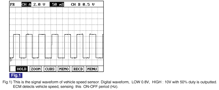
Sensing Type | LOW Signal Voltage | HIGH Signal Voltage | Signal Duty |
Hall sensor type | below 1.5V | above 3.5V | 50±5% |
Connect Scantool to Data Link Connector (DLC).
Warm engine up to normal operating temperature.
Turn "OFF" electrical devices and A/C.
Monitor "VEHICLE SPEED SENSOR " parameter on the Scantool.
specification : current vehicle speed is displayed.
Electrical systems consist of a lot of harness and connectors, poor connection of terminals can cause various problems and damge of component.
Perform checking procedure as follows.
Check damage of harness and terminals : Check terminals for contact resistance, corrosion and deformation.
Check connecting condition of ECM and component connector : Check terminal seperation, damage of locking device and connecting condition between terminal and wiring.
Disconnect the pin which requires checking at male connector and insert it to the terminal at female connector for checking connecting condition. ( after checking, reconnect the pin at correct position. )
Is the problem found?

▶ Repair the trouble causing part and go to "Verification of Vehicle Repair".

▶ Go to "Power Circuit Inspection".
Check power circuit voltage
IG KEY "OFF", ENGINE "OFF"
Disconnect Vehicle Speed Sensor connector.
IG KEY "ON"
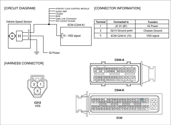
Measure the voltage of VSS connector terminal 1.
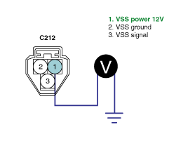
Specification : 11.5V~13.0V
Is the measured voltage within the specification?
▶ Go to "Signal Circuit Inspection".
▶ Repair E/R JUNCTION BOX 10A FUSE and related circuit, and go to "Verification of Vehicle Repair".
Check signal circuit voltage (sensor side)
IG KEY "OFF", ENGINE "OFF"
Disconnect Vehicle Speed Sensor connector.
IG KEY "ON"
Measure the voltage of VSS connector terminal 3.
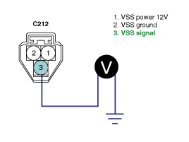
Specification : 8.0V~11.5V
Is the measured voltage within the specification?
▶ Go to "2. Check signal circuit voltage (ECM side)".
▶ Repair poor connection or open in joint connector M-1 terminal 1 related circuit and go to "Verification of Vehicle Repair".
Check signal circuit voltage (ECM side)
IG KEY "OFF", ENGINE "OFF"
Disconnect Vehicle Speed Sensor connector and ECM connector.
IG KEY "ON"
Measure the voltage of ECM connector(C244-K) terminal 75.
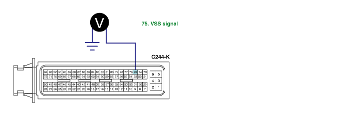
Specification : 8.0V~11.5V
Is the measured voltage within the specification?
▶ Go to "Ground Circuit Inspection".
▶ Repair poor connection or open in joint connector M-1 terminal 1 related circuit and go to "Verification of Vehicle Repair".
IG KEY "OFF", ENGINE "OFF"
Disconnect VSS connector.
IG KEY "ON"
Measure the voltage of VSS connector terminal 3. [ TEST "A" ]
Measure the voltage between VSS connector terminal 3 and 2. [ TEST "B" ]
( terminal 3 : Check + prove , terminal 2 : Check - prove )
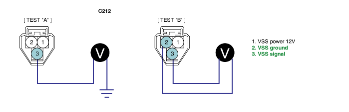
Specification : [TEST "A"] Voltage - [TEST "B"] Voltage = below 200mV
Is the measured voltage within the specification?
▶ Go to "Component Inspection".
▶ When "B" voltage is not detected : Repair open in ground circuit and go to "Verification of Vehicle Repair".
▶ When the voltage difference between "A" and "B" is above 200mV : Eliminate the causes of excessive resistance and go to "Verification of Vehicle Repair".
IG KEY "OFF", ENGINE "OFF".
Disconnect VSS connector.
Disconnect VSS and Driven gear assy'.
Check rotating state of VSS driven gear.
Connect VSS connector and IG KEY "ON".
Rotate Driven gear with hand.
Specification : Vehicle Speed Signal generates.
Does vehicle speed signal generate?
▶ Go to "Verification of Vehicle Repair".
▶ Replace vehicle speed sensor and go to "Verification of Vehicle Repair".
After a repair, it is essential to verify that the fault is corrected.
After connecting Scantool select "DIAGNOSTIC TROUBLE CODES(DTCs)" mode.
Clear recorded DTC using Scantool.
Drive the vehicle within DTC "Enable conditions" in "General information".
After selecting "DIAGNOSTIC TROUBLE CODES(DTCs)" mode and check if DTC is recorded again.
Are any DTCs recorded ?
▶ Go to the DTC guide of recorded NO. in Scantool.
▶ System operates within specification.
