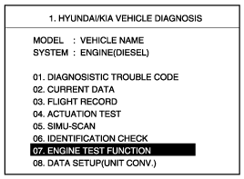
Connect Scan tool to the DLC and select "Vehicle" and "Engine Test Function".
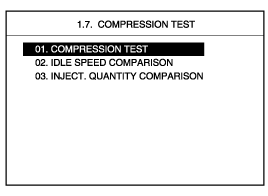
COMPRESSION TEST
IDLE SPEED COMPARISON
INJECT QUANTITY COMPARISON
Connect Scan tool to the DLC and select "Vehicle" and "Engine Test Function".

Information for ECM version is displayed as below.
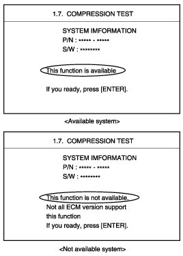
After pressing "[ENTER]" select "COMPRESSION TEST" mode and press "[ENTER]".
Set the test condition described as below screen and then, crank engine. When engine stop message being appeared, stop cranking.
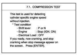
Press "ANAL" and the test result is appeared.
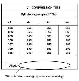
During cranking engine does not start.
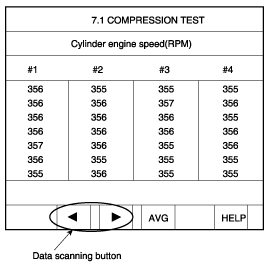
Press "AVG" and the data average of each cylinder is appeared.
Press "HELP" and description of the data is appeared.
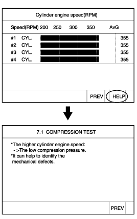
After pressing "ESC", select "IDLE SPEED COMPARISON" and press "[ENTER]".
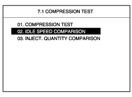
Set the test condition described as below screen and press "[ENTER]".
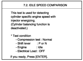
The rpm data of each cylinder is appeared.
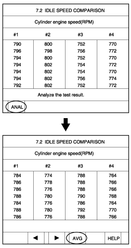
Press "AVG" and teh data average of each cylinder is appeared.
Press "HELP" and description of the data is appeared.
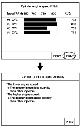
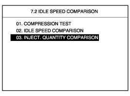
After pressing "ESC", select "INJECT QUANTITY COMPARISON" and press "[ENTER]".
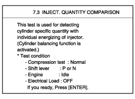
Set the test condition described as below screen and press "[ENTER]".
The data of each cylinder about RPM and compensating injection quantity is appeared.
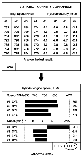
Press "HELP" and description of the data is displayed as below.
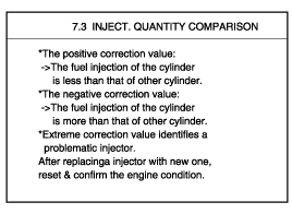
Replace the default injector, and then repeat previous test modes to check if the injector is normal.
Turn ignition switch OFF.
Disconnect the injector connector.
Measure resistance between terminal 1 and 2.
Specification : 0.33Ω at 20℃(68℉)
Common Rail Fuel Injection System is subject to extremely high pressure (Approximately 1,600 bar)
Never perform any work on injection system with engine running or within 30 seconds after the engine stops.
Always pay attention to safety precaution.
Ensure the absolute cleanliness.
It is not recommended to remove the injectors without any notice.
Disconnect the injector connector (A).
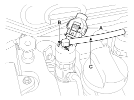
After removing the clip (B), disconnect the retun hose (C) from the injectors
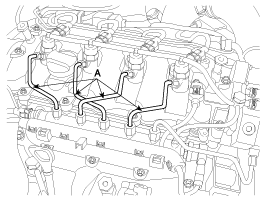
Disconnect the high pressure pipe (A) connecting the injectors with the common rail.
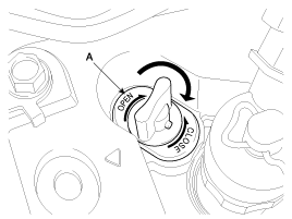
Rotate the lever (A) clockwise and pull it upward.
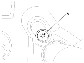
Unscrew the clamp tightening bolt (A) and pull the injector upward with the "Injector Remover" and the "Injector Remover Adapter" (Refer to "SPECIAL SERVICE TOOL" section).
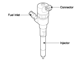
Install the injector according to the reverse order of "REMOVAL" procedure.
When installing the injector, MUST REPLACE the O-ring (A) and apply a grease to that.
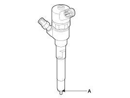
When installing the high pressure pipe, apply the specified tightening torques to the flange nuts of the injectors and the common rail side with SST (Refer to below table).
Item | Dimension | SST No. |
Flange Nut (Injector Side) | 14 mm (0.551 in) | 09314-27110 |
Flange Nut (Common Rail Side) | 17 mm (0.669 in) | 09314-27120 |
· Injector clamp mounting bolts: 24.5 ~ 28.4 N·m (2.5 ~ 2.9 kgf·m, 18.1 ~ 20.1 lbf·ft)
· High pressure pipe flange nuts (Injectors ↔ Common Rail): 24.5 ~ 28.4 N·m (2.5 ~ 2.9 kgf·m, 18.1 ~ 20.1 lbf·ft)
After replacing (an) injector(s), MUST input the injector data (7 digit) into the ECM.
Turn ignition switch OFF.
Replace the injector with a new one according to the "REMOVAL" and "INSTALLATION" procedures.
Connect a scan tool to Data Link Connector (DLC) and turn ignition switch on.
Select "ENGINE CONTROL".
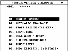
Select "MANUAL SELECTION MODE".
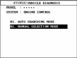
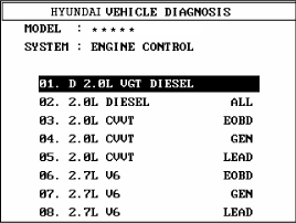
Select "D 2.0L VGT DIESEL".
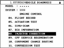
Select "INJECTOR CORRECTION".
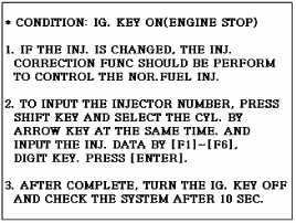
Press "ENTER" key.
Input the injector data (7 digit) written on the top of each injector with function keys ([F1] ~ [F6]) and number keys.
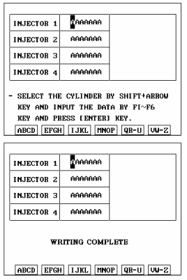
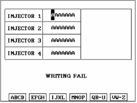
When "WRITING FAIL" is displayed on the scan tool, input injector data (7 digits) of each cylinder into a new ECM again as prior procedure.
