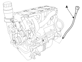
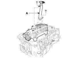
Remove the engine oil level gauge(A).
Remove the engine and transaxle assembly from the vehicle.
Remove the transmission from the engine and transaxle assembly by loosening bolts.
Remove the eight flywheel bolts, then separate the flywheel from the crankshaft flange.
Remove the timing belt assembly.
Remove the intake and the exhaust manifold.
Remove the cylinder head assembly.
Remove the alternator. (See EE group - alternator)
Remove the engine oil level gauge(A).

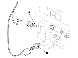
Remove the CKP(Crankshaft Position Sensor)(A) and the oil pressure switch(B).
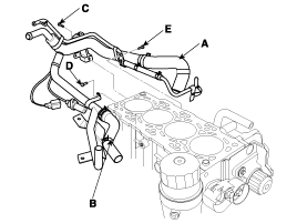
Remove the heater and oil cooler return pipe assembly(A) after loosening the hose clamps(B) and the bolts(C, D, E).
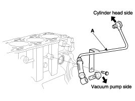
Remove the tube(A) between the vacuum pump and the cylinder head.
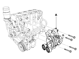
Remove the power steering pump mounting bracket assembly(A).
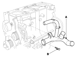
Remove the water inlet pipe assembly(A) by loosening a bolt(B) and clamps.
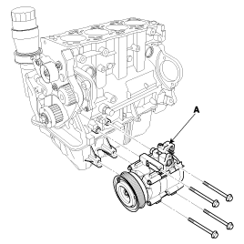
Remove the air compressor(A). (See HA group - compressor)
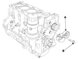
Remove the auto-tensioner(A) by loosening the bolt(B).
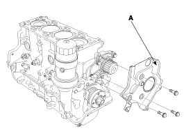
Remove the timing belt rear cover(A).
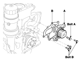
Remove the water pump assembly(A) with the gasket(B).
Remove the oil pan(A) after removing the oil-pan acoustic shield.
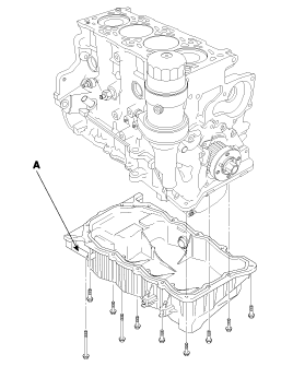
An oil-pan acoustic shield can be also removed when removing a transmission from an engine.
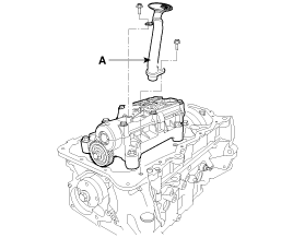
Remove the oil screen(A) for removal of the oil pump case.
Remove the crankshaft bolt(A), then seperate the crankshaft sprocket(B).
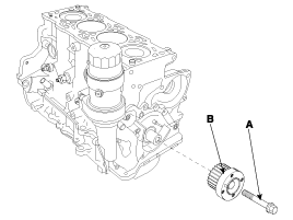
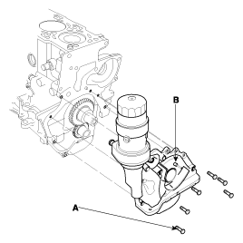
Remove the oil-pump assembly(B) by loosening the bolts(A).
Crankshaft Bore Code Location
Letters have been stamped on the end of the block as a code for the size of each of the 5 main journal bores. Write down the crank bore codes.
If you can't read the codes because of accumulated dirt and dust, do not scrub them with a wire brush or scraper. Clean them only with solvent or detergent.
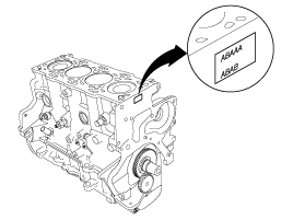
Discrimination of cylinder block
Discrimination | SIZE (mm) (Inside diameter of crank bore) | |
Class | Mark | |
A | A | Ø64 (0 ~ +0.006) |
B | B | Ø64 (+0.006 ~ +0.012) |
C | C | Ø64 (+0.012 ~ +0.018) |
Main Journal Code Locations
The main Journal Codes are stamped on the No.1 web.
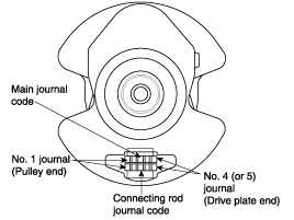
Discrimination of crank shaft
Discrimination | SIZE (mm) (Outside diameter of main journal) | |
Class | Mark | |
I | A | Ø60 (+0.014 ~ +0.020) |
II | B | Ø60 (+0.008 ~ +0.014) |
III | C | Ø60 (+0.002 ~ +0.008) |
Use the crank bore codes and crank journal codes to select the appropriate replacement bearings from the following table.
Color code is on the edge of the bearing. Refer to the table in the step 6 of the main bearing clearance inspection.
When using bearing halves of different colors, it dose not matter which color is used in the top or bottom.
Installing procedure of bearing
Shaft bore combination | Bearing mark | Oil clearance | |
Shaft mark | Bore mark | ||
I (A) | A (A) | A (BLUE) | 0.024 ~ 0.042 mm |
B (B) | B (BLACK) | ||
C (C) | C ( - ) | ||
II (B) | A (A) | B (BLACK) | |
B (B) | C ( - ) | ||
C (C) | D (GREEN) | ||
III (C) | A (A) | C ( - ) | |
B (B) | D (GREEN) | ||
C (C) | E (YELLOW) | ||
Inspect each connecting rod for cracks and heat damage.
Connecting Rod Big End Bore Code Locations
Each rod has tolernance range from 0 to 0.018mm (0.0007in.), in 0.006mm (0.0002in.) increments, depending on the size of its big end bore. It's then stamped with a letter (A, B or C) indicating the range. You may find any combination of letters in any engine.
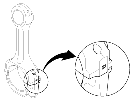
Discrimination connecting rod
Discrimination | SIZE (mm) (Inside diameter of connecting rod big end bore) | |
Class | Mark | |
A | A | Ø 53 (0 ~ +0.006) |
B | B | Ø 53 (+0.006 ~ +0.012) |
C | C | Ø 53 (+0.012 ~ +0.018) |
Connecting Rod Journal Code Locations
The connecting Rod Journal Codes are stamped on the No. 1 web.
)

Discrimination of crank shaft pin
Discrimination | SIZE (mm) (Outside diameter of pin) | |
Class | Mark | |
I | A | Ø50 (+0.020 ~ +0.026) |
II | B | Ø50 (+0.014 ~ +0.020) |
III | C | Ø50 (+0.008 ~ +0.014) |
Use the big end bore codes and rod journal codes to select appropriate replacement bearings from the following table.
Color code is on the edge of the bearing.
Refer to the table in the step 5 of rod bearing clearance inspection.
Shaft bore combination | Bearing mark | Oil clearance | |
Sahft mark | Bore mark | ||
I | A (A) | A (BLUE) | 0.024 ~ 0.042 mm |
B (B) | B (BLACK) | ||
C (C) | C (WHITE) | ||
II | A (A) | B (BLACK) | |
B (B) | C (WHITE) | ||
C (C) | D (GREEN) | ||
III | A (A) | C (WHITE) | |
B (B) | D (GREEN) | ||
C (C) | E (YELLOW) | ||
Apply engine oil to the piston pin snap rings and turn them in the ring grooves.
Take care not to damage the ring grooves.
Remove both snap rings(A) carefully so they do not go flying or get lost. Wear eye protection.
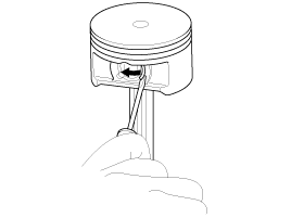
Remove the piston pin and the conecting rod assembly.
Measure the diameter of the piston pin.
Piston Pin Diameter
Standard (New)
27.995 ~ 28.000mm (1.1022 ~ 1.1024in.)
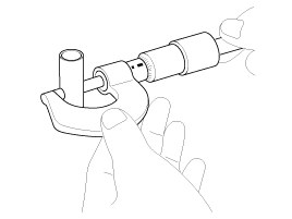
Inspect the piston, piston pin and connecting rod when they are at room temperature.
Set a snap ring in one side of piston pin hole.
Before inserting the piston pin, apply a sufficient amount of the lubricant oil to the outer surface of the piston, the inner surface of the piston pin hole and the small end bore of the connecting rod.
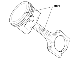
Insert the piston pin(A). Assembly the piston and connecting rod with the embossed front marks on the same side.
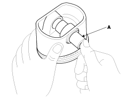
The front mark of the piston is embossed on the piston whereas some letters are located on a side surface of the connecting rod as the front mark.
Be sure to keep the small end bore, piston pin hole and piston pin undamaged and unscratched when inserting the piston pin.
Set the snap rings to be sure for contacting with the groove of the piston pin hole.
Using a piston, push a new ring into the cylinder bore.
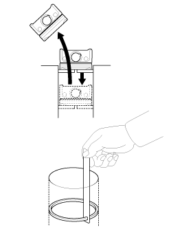
Measure the piston ring end-gap(B) with a feeler gauge :
If the gap is too small, check to see if you have the proper rings for your engine.
If the gap is too large, recheck the cylinder bore diameter against the wear limits.
If the bore is over the service limit, the cylinder block must be rebored.
Piston Ring End-Gap
Top ring
Standard (New) : 0.25 ~ 0.40mm (0.0098 ~ 0.0157in.)
Second Ring
Standard (New) : 0.40 ~ 0.60mm (0.0157 ~ 0.0236in.)
Oil Ring
Standard (New) : 0.20 ~ 0.40mm (0.008 ~ 0.016in.)
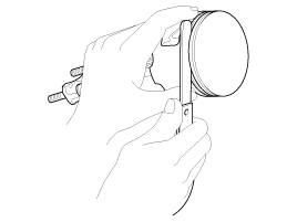
After installing a new set of rings, measure the ring-to-groove clearances :
Top Ring Clearance
Standard (New)
0.083 ~ 0.137mm (0.0033 ~ 0.0054in.)
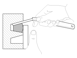
Second Ring Clearance
Standard (New)
0.065 ~ 0.110mm (0.00256 ~ 0.00433in.)
Oil Ring Clearance
Standard (New)
0.03 ~ 0.07mm (0.00118 ~ 0.00275in.)
Clean and dry the oil pump mating surface.
Install the oil pump
Install a new crankshaft oil seal in the oil pump.
Apply liquid gasket evenly to the block mating surface of the oil pump.
Standard liquid gaskets (or sealants)
LOCTITE5900 or equivalent
● Apply liquid gasket in a wide bead : 2.5 ± 0.5m ● Apply the liquid gasket without stoping. ● Assemble the oil pump within 5 minutes after applying. |
Grease the lips of the oil seals.
Align the inner rotor with the crankshaft drive gear and install the oil pump(B).
Tightening torque(A)
20 ~ 27N.m (2.0 ~ 2.7kgf.m, 14.75 ~ 19.91lb-ft)

Clean the excess grease off the crankshaft and check the seals for distortion.
Install the crankshaft key(A) on the crankshaft assembly.
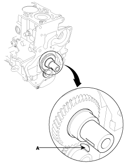
Insert the crankshaft sprocket(B) then tighten the crankshaft bolt(A).
Tightening torque
196.1 ~ 205.9N.m (20.0 ~ 21.0kgf.m, 144.7 ~ 151.9lb-ft)
Align the timing mark on the sproket.

Install the oil screen(A) on the oil pump case(B) and the engineblock.
Tightening torque
10 ~ 12N.m (1.0 ~ 1.2kgf.m, 7.37 ~ 8.85lb-ft)
The bolt B should be tightened after the installation of the bolt A.
Clean and dry the bed plate and the oil pan mating surfaces.
Apply liquid gasket evenly to the bed plate mating surface of the oil pan. Install the oil pan.
Standard liquid gasket : LOCTITE 5900
Assemble the oil pan in 5 mimutes after applying the liquid gasket.
Apply liquid gasket in a 3mm wide bead without stopping.
The clearance between the liquid gasket and the flange inner end should be 2 ~ 3mm.
Tighten the bolt in two or three steps. In the final step, tighten all bolts.
Tightening torque
10 ~ 12N.m (1.0 ~ 1.2kgf.m, 7.38 ~ 8.851lb-ft)

After installing the oil pump assembly and the oil pan, remove the oil cooler and fill the 50cc engine oil.
Install the water pump.
Install the auto-tensioner(A).

Install the air compressor(A). (See HA group - compressor)

Install the water inlet pipe assembly(A), tightening the bolt(B).
Tightening torque
20 ~ 25N.m (2.0 ~ 2.5kgf.m, 14.75 ~ 18.44lb-ft)

Install the power steering pump mounting bracket assembly(A).

Install the heater and oil cooler return pipe(A) assembly.
Tightening torque
Rear side bolt and left side bolt(C, D)
20 ~ 25N.m (2.0 ~ 2.5kgf.m, 14.75 ~ 18.44lb-ft)
Right side bolt(E)
8 ~ 10N.m (0.8 ~ 1.0kgf.m, 5.90 ~ 7.38lb-ft)

Install the CKP(Crankshaft Position Sensor)(A) and the oil pressure switch(B).
Tightening torque
(A) : 3.9 ~ 5.9N.m(0.4 ~ 0.6kgf.m, 2.9 ~ 4.3lb-ft)
(B) : 14.7 ~ 21.6N.m(1.5 ~ 2.2kgf.m, 10.8 ~ 15.9lb-ft)

Install the cylinder head assembly.
Install the intake/exhaust manifold assemblies.
Install the oil level gauge(A).
Tightening torque
10 ~ 12N.m (1.0 ~ 1.2kgf.m, 7.38 ~ 8.85lb-ft)

Install the timing belt assembly.
Remove the balance shaft assembly(A).
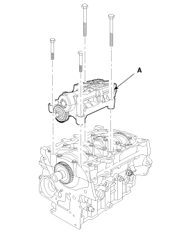
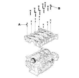
Remove the bed plate assembly.
Remove the bolts(A).
To prevent warpage, unscrew the bolts in sequence 1/3 turn at a time : repeat the sequence until all bolts are loosened.
Remove the bolts(B).
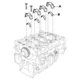
Remove the connecting rod bearing caps(A) and bearings(B).
After removing No. 1 and 4 connecting rod bearing caps and turn the crankshaft No. 2 and 3 crankpins are at the top.
Remove the rest bearing caps and bearings.
Keep all caps/bearings in order.
If you can feel a ridge of metal or hard cabon around the top of each cylinder, remove it with a ridge reamer. Follow the reamer manufacturer's instructions. If the ridge is not removed, it may damage the pistons as they are pushed out.
Drive out the piston assembly from the engine block.
Reinstall the connecting rod bearings and caps after removing each piston/connecting rod assembly.
To avoid mixup on reassembly, mark each piston/connecting rod assembly with its cylinder number.
Lift the crankshaft(A) out of the engine block(B), being careful not to damage the journals.
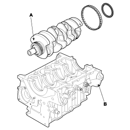
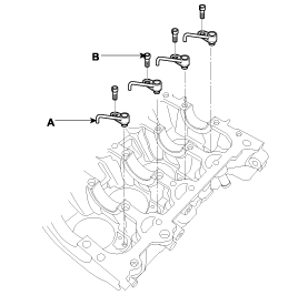
Remove the piston oil jet(A) by loosening the hexagonal bolt(B) with a hexagonal wrench.
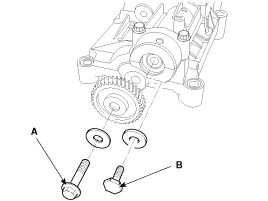
Remove the balance shaft intermediate gear bolt(A) and dive gear bolt(B).
Remove the balance shaft lower carrier.
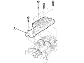
Remove the balance driven shaft(A) and balance dive shaft(B).
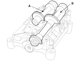
Remove the balance shaft bearing(B) from balance shaft upper carrier(A).
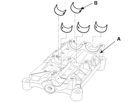
Inspect ring gear teeth for wear or damage.
Flywheel bolts should be free from detrimental flaws.
Measure the connecting rod end play with a feeler gauge(A) between the connecting rod(B) and crankshaft(C).
Connecting Rod End play
Standard (New) : 0.10 ~ 0.35mm (0.004 ~ 0.014in.)
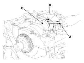
If the connecting rod end play is out-of-tolerance, install a new connecting rod, and recheck. If it is still out-of-tolerance, replace the crankshaft.
If the end play is excessive. Replace parts as necessary.
To check main bearing-to-journal oil clearance, remove the bed plate, the crankshaft and the bearing halves.
Clean each main journal and bearing half with a clean shop towel.
Cut plastigauge to the same length as the width of the bearing.
Place one strip of plastigauge across each main journal on the cylinder block and the bed plate, avoiding the oil holes.
Reinstall the bearings, crankshaft and bed plate then torque the bolts to the specified valve.
Do not rotate the crankshaft during inspection.
Remove the bed plate and bearings again and measure the widest part of the plastigauges with a calibrated scale on which an arrow of marks has beeen printed.
Main bearing-to-journal Oil Clearance
Standard (valve)
0.024 ~ 0.042mm (0.0009 ~ 0.0017in.)
Discrimination of crankshaft main bearing
Discrimination | SIZE (mm) (Thickness of bearing) | Place of identification mark | |
Class | Mark | ||
E | YELLOW | 1.987~1.990 | 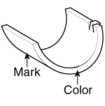 |
D | GREEN | 1.984~1.987 | |
C | - | 1.981~1.984 | |
B | BLACK | 1.978~1.981 | |
A | BLUE | 1.975~1.978 | |
If the plastigauge mesaure too wide or too narrow, remove the crankshaft, and remove the upper half of the bearing. Install a new, complete bearing with the same color code(s), and recheck the clearance. Do not file, shim, or scrape the bearings to adjust clearance.
If the plastigauge shows the clearance is still incorrect, try the next larger or smaller bearing (the color listed above or below that one), and check again. If the proper clearance cannot be obtained by using the appropriate larger or smaller bearings, replace the crankshaft and start over.
Remove the connecting rod cap and bearing half.
Clean the crankshaft rod journal bearing half with a clean shop towel.
Place pastigauge across the rod journal.
Reinstall the bearing half and cap, and torque the bolt.
Do not rotate the crankshaft during inspecition.
Remove the rod cap and bearing half and measure the widest part of the plastigauge.
Connectinng Rod Bearing-to-Journal Oil
Clearance : 0.024 ~ 0.042mm (0.0009 ~ 0.0017in.)
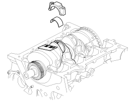
If the plastigauge measure too wide or too narrow, remove the upper half of the bearing, install a new, complete bearing with the same color code(s), and recheck the clearance. Do not file, shim, or scrape the bearings or the caps to adjust clearance.
Discrimination of connecting rod bearing
Discrimination | Size (Thickness of bearing) | Place of Identification | |
Class | Mark | ||
E | YELLOW | 1.484 ~ 1.487 |  |
D | GREEN | 1.481 ~ 1.484 | |
C | WHITE | 1.478 ~ 1.481 | |
B | BLACK | 1.475 ~ 1.478 | |
A | BLUE | 1.472 ~ 1.475 | |
If the plastigauge shows the clearance is still incorrect, try the next larger or smaller bearins (the color listed above or below that one), and check clearance again. If the proper clearance cannot be obtained by using the appropriate larger or smaller bearing, replace the crankshaft and start over.
Check the piston for distortion or cracks.
Measure the piston diameter at a point 10mm (0.4in) from the bottom of the skirt. There are three standard-size pistons (A. B and C). The letter is stamped on the top of the piston. Letters are also stamped on the block as cylinder bore sizes.

Piston Diameter and Cylinder Bore
Standard value :
Grade | A | B | C |
Piston Outer Diameter (mm) | 86.92 ~ 86.93 | 86.93 ~ 86.94 | 86.94 ~ 86.95 |
Cylinder Bore (mm) | 87.00 ~ 87.01 | 87.01 ~ 87.02 | 87.02 ~ 87.03 |
Clearance (mm) | 0.070 ~ 0.090 | ||
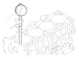
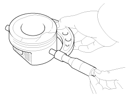
Scored or scratched cylinder bores must be honed.
Check the top of the block for warpage. Measure along the edges and across the center.
Engine Block Warpage
Standard (New)
0.042mm (0.00165in.) for width
0.096mm (0.00378in.) for legth
0.012mm (0.00047in.)/50×50mm
Only a scored or scratched cylinder bore must be honed.
Measure the cylinder bores.
If the block is to be reused, hone the cylinders and remeasure the bores.
Hone the cylinder bores with honing oil and a fine stone. Do not use stones that are worn or broken.
When honing is complate, thoroughly clean the engine block of all metal particles. Wash the cylinder bores with hot soapy water, then dry and oil them immediately to prevent rusting. Never use solvent, it will redistribute the grit on the cylinder walls.
If scoring or scratches are still present in the cylinder bores after honing to the service limit, rebore the cylinder block. Some light vertical scoring and scratching is acceptable if it is not deep enough to catch your fingernail and does not run the full length of the bore.
Install the balance shaft bearing(B) to the balance shaft upper carrier(A).

Install the balance driven shaft(A) and the balance driver shaft(B).
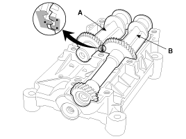
Confirm the gear marks.
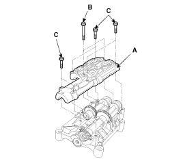
Install the balance shaft lower carrier(A) after installing the balance bearing to the lower carrier.
Tightening torque
Bolt(B) : 52 ~ 54N.m (5.2 ~ 5.4kgf.m, 37.6 ~ 39.1lb-ft)
Bolts(C) : 28 ~ 32N.m (2.8 ~ 3.2kgf.m, 20.3 ~ 23.1lb-ft)
Install the balance shaft drive gear bolt(B) and the intermediate gear bolt(A).
Tightening torque
Bolts(A) : 20N.m (2.0kgf.m, 14.5lb-ft, 14.5lb-ft) ± 40°
Bolts(B) :39 ~ 43N.m (3.9 ~ 4.3kgf.m, 28.2 ~ 31.1lb-ft)

Confirm the gear marks.
Remove the connecting rod caps then install the ring compressor and check that the bearing is securely in place.
Position the marks facing the timing belt side of the engine.
Position the piston in the cylinder and tap it in using the wooden handle of hammer.
Maintain downward force on the ring compressor to prevent the rings from expanding before entering the cylinder bore.
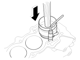
Stop after the ring compressor pops free, and check the connecting rod-to-crank journal alignment before pushing the piston into place.
Check the connecting rod bearing clearance with plastigauge.
Apply engine oil to the bolt threads, then install the rod caps with bearings.
Install the oil jets, tightening the hexagon socket head bolts with the torque 10 ~ 13Nm (0.1 ~ 1.3kgf.m, 7.2 ~ 9.4lb-ft)
Apply a coat of engine oil to the main bearings.
Install the bearing halves in the engine block.
Hold the crankshaft so rod journal No. 2 and rod journal No. 3 are straight up.
Lower the crankshaft into the block.
Install the bearing halves in the bed plate after applying a coat of engine oil.
Install the bed plate(C) to the engine block. After applying the sealant (LOCTITE 5205, DREIBOND 5105 or HYLOMAR 3000).
Tightening torque
15mm(B)
27.5 ~ 31.4 N.m (2.8 ~ 3.2 kgf.m, 20.3 ~ 23.1 lb-ft) + 120°
12mm(A)
33.7 ~ 37.7 N.m (3.3 ~ 3.7kgf.m, 24.9 ~ 27.8 lb-ft)
Always use new bearing cap bolts.

Rotate the crankshaft clockwise to be seated properly.
Check the main bearing clearance with plastigauge.
Install the piston and connecting rod assemblies.
Apply coat of engine oil to the connecting rod bearings.
Install the bearing halves in the connecting rods.
Insert the assemblies into the cylinder bores.
Install the connecting rod caps and bolts finger tight
Rotate the crankshaft clockwise, seat the journals into connecting rod No.2 and connecting rod No.3. Install the connecting rod caps and bolts finger tight. Install caps so the bearing recess is on the same side as the recess in the rod.
Check the connecting rod bearing clearance with plastigage.
Apply engine oil to the bolt threads, then install the rod caps within bearings and torque the bolts to 24.5 N.m + 90° (2.5 kgf.m + 90°, 18.1 lb-ft + 90°).
Using the SST(09231-27000), install the crankshaft oil seal(A) squarely.
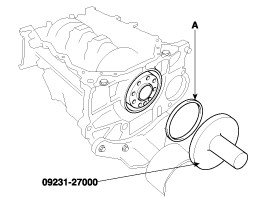
Clean and dry the mating surfaces.
Apply a light coat of oil to the crankshaft and to the lip of the seal.
Install the balance shaft assembly(A) onto the bed plate with the bolts (B,C).

Tightening torque
53 ~ 57N.m (5.3 ~ 5.7kgf.m, 39.09 ~ 42.04lb-ft)
Pay attention to the timing marks on the driver gears of the balance shaft and the crankshaft.