3.
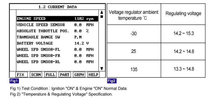
Monitor the "BATTERY VOLTAGE" parameter on the scantool.
Specification : Approx. 14.5 ± 0.3 V (25°C)
The ABS ECU(Electronic Control Unit) checks the battery voltage to determine, as a safety issue, whether the ABS system can operate normally or not. The normal battery voltage range is essential for controlling the ABS system as instended.
The ABS ECU monitors battery voltage by reading the value of voltage. When the voltage is higher than the expected normal value, this code is set, and the ABS/EBD/ESP functions are prohibited. If the voltage recovers, to within normal operating ranges, then the controller returns to normal operation as well.
Item | Detecting Condition | Possible cause |
DTC Strategy | ● Battery Voltage Monitoring | ● Poor connection in power supply circuit (IGN+) ● Faulty Alternator ● Faulty HECU |
Monitoring Period | ● Continuous (Over voltage faults will be always stored.) | |
Enable Conditions | ● When Vign is higher than 16.8 V. - If the voltage is recovered to 16.6 V, the controller returns to normal state. - The monitored supply voltage is filtered and limited to a rise time of 4 volts per second. | |
Fail Safe | ● The ABS/EBD/ESP functions are inhibited. - The proper function of valves and return pump is not guaranteed. ● The ABS/EBD/ESP warning lamps are activated. ● The supply voltage to wheel speed sensor is interrupted. |
Connect scantool to Data Link Connector(DLC)
Engine "ON".
Monitor the "BATTERY VOLTAGE" parameter on the scantool.
Specification : Approx. 14.5 ± 0.3 V (25°C)
Is parameter displayed within specifications?

▶ Fault is intermittent caused by poor connection in power harness (IGN+) and/or HECU's connector or was repaired and HECU memory was not cleared. Thoroughly check connectors for looseness, poor connection, bending, corrosion, contamination, deterioration, or damage. Repair or replace as necessary and then go to "Verification of Vehicle Repair" procedure.

▶ Go to "W/Harness Inspection" procedure.
Many malfunctions in the electrical system are caused by poor harness(es) and terminals. Faults can also be caused by interference from other electrical systems, and mechanical or chemical damage.
Thoroughly check connectors for looseness, poor connection, bending, corrosion, contamination, deterioration, or damage.
Has a problem been found?
▶ Repair as necessary and then go to "Verification of Vehicle Repair" procedure.
▶ Go to "Alternator Output Voltage Inspection" procedure.
Engine "ON".
Measure voltage between the battery terminal(+) and the battery terminal(-).
Specification : Approx. 14.5 ± 0.3 V (25 °C)
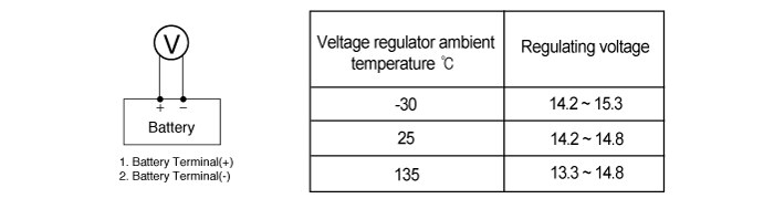
Is the measured voltage within specifications?
▶ Go to "Power Circuit Inspection" procedure.
▶ Check for damaged harness and poor connection between alternator and battery. If OK repair or replace alternator and then go to "Verification of vehicle Repair" procedure.
Engine "ON".
Measure voltage between the battery terminal(+) and terminal "28" of the HECU harness connector.
Specification : Approx. below 0.2 V
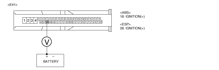
Is the measured voltage within specifications?
▶ Go to "Ground Circuit Inspection" procedure.
▶ Check for damaged harness and poor connection between the battery terminal(+) and terminal "28" of the HEC Uharness connector. Repair as necessary and then go to "Verification of vehicle Repair" procedure.
Ignition "OFF".
Disconnect HECU connector.
Measure resistance between terminal "4" of the HECU harness connector and chassis ground.
Specification : Approx. below 1 Ω
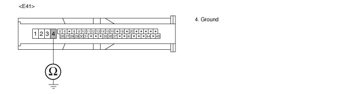
Is the measured resistance within specifications?
▶ Go to "Component Inspection" procedure.
▶ Check for damaged harness and poor connection between terminal "4" of the HECU harness connector and chassis ground. Repair as necessary and then go to "Verification of vehicle Repair" procedure.
Ignition "OFF"
Engine "ON".
Does warning lamp remain On?
▶ Substitute with a known-good HECU and check for proper operation. If problem is corrected, replace HECU and then go to "Verification of Vehicle Repair" procedure.
▶ Fault is intermittent caused by poor connection in power harness (IGN+), faulty Alternator and/or faulty HECU or was repaired and HECU memory was not cleared. Go to the applicable roubleshooting procedure.
After a repair, it is essential to verify that the fault has been corrected.
Connect scantool and select "Diagnostic Trouble Codes(DTCs)" mode
Using a scantool, Clear DTC.
Operate the vehicle within DTC Detecting Condition in General Information
Are any DTCs present?
▶ Go to the applicable troubleshooting procedure.
▶ System performing to specification at this time.
