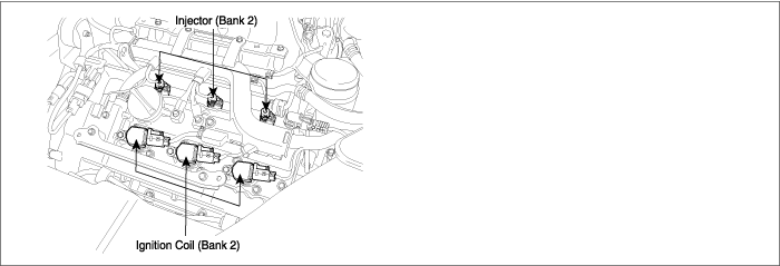
COMPONENT LOCATION
GENERAL DESCRIPTION

Misfires can be caused by lack of combustion in a cylinder due to absence of spark, poor fuel metering, poor compression, or many other causes. Even a small number of misfires may result in excessive exhaust emissions due to the unburned mixture. Increased misfire rates cause damage to the catalytic converter. The PCM monitors the crankshaft speed variation to determine if any misfiring generated. The PCM identifies the specific cylinder in which the misfire has occurred and counts individual misfire events by monitoring changes in the crankshaft rotation for each cylinder. A random misfire indicates two or more cylinders are misfiring.

DTC DESCRIPTION

The PCM measures reference event times and calculates the positive and negative acceleration of the crank wheel to detrmine whether a misfire has occurred.

When the rate of misfire exceeds a threshold where the catalyst reaches a temperature where permanent damage can ocur. PCM sets this DTC. In case that misfire affects Catalyst damage, MIL(Malfunction Indication Lamp) will be illuminating and blinking at 1HZ frequency. However, In case of Indivisual and Emission damaging misfire, MIL will be turned on when the malfunction is detected.

Especially, if injector connector is disconnected for more than 46 sec., PCM sets DTC relating to misfire and conducts the fuel-cut to protect the catalyst.

DTC DETECTING CONDITION

Item

Detecting Condition

Possible Cause

DTC Strategy

Determine if a multiple cylinder misfire or a cylinder specific misfire is occurring by monitoring crankshaft acceleration.

Faulty Spark plugs

Faulty Spark plug cables

Air Leakage

Belt deflection and Air gap of CKPS

Incorrect timing

Faulty injector

Improper fuel pressure

Improper engine compression

Faulty PCM

Enable condition

No sudden change in throttle opening

Torque management control is not functioning

Not deceleration fuel cut off

Not fuel cut off during high speed operation

Not negative torque driving conditions

Not fuel level low

TEC is learned

Coolant temperature is outside the window

500〈 Engine speed〈 6600

11〈 Battery vlotage〈 16

TPS/MAP sensor/CAMS/CKPS/ECT sensor are normal

Thresh old value

Case 1

Individual event misfire detection 〉 Threshold

Case 2

Emissions damaging 〉Threshold

Case 3

Catalyst damaging 〉 Threshold

Diagnosis time

Continuous

MIL ON condition

2 driving cycles

MONITOR SCANTOOL DATA
1.

Is the power balance test done?

▶ If injector connector for power balance test is disconnect for over 46 sec., this can cause DTC relating to misfire. Stop the test and connect it and delete DTC and then go to "Verification of Vehicle repair" procedure.

▶ If power balance test is finished within 46 sec., go to next procedure.

▶ Go to "Monitor scantool data" as follows.
2.

Monitor scantool data

(1)

Ignition "OFF"

(2)

Connect Scantool and Engine "ON"

(3)

Monitor parameters related to " Cylinder 5 Misfire Detected" on CURRENT DATA

Specification :

Ignition

BTDC 10° ± 5°

Idle speed

N-range

720 ± 100 rpm

D-range

650 ± 100 rpm

(4)

Are the parameters related to "Cylinder 5 Misfire Detected" displayed correctly on Current Data ?

▶ Fault is intermittent caused by poor contact in the sensor’s and/or PCM’s connector or was repaired and PCM memory was not cleared. Thoroughly check connectors for looseness, poor connection, bending, corrosion, contamination, deterioration, or damage. Repair or replace as necessary and go to "Verification of Vehicle Repair" procedure

▶ Go to "System Inspection " procedure

SYSTEM INSPECTION
1.

Check Spark Pulg

(1)

Remove cylinder’s spark plugs

(2)

Visually/physically inspect the following items:

- Damaged insulation, Worn electrodes, Oil or fuel fouled, Loose terminals and cracks

- Check for plug gap : 1.0 - 1.1 mm (0.039 - 0.043 in.)

- Check if the spark plug for the relevant cylinder is lighter in color than the other plugs.

(3)

Has a problem been found in any of the above areas?

▶ Repair or replace as necessary and go to "Verification of Vehicle Repair" procedure

▶ Go to "Check Air Leakage " as below

2.

Check Air Leakage

(1)

Visually/physically inspect the air leakage in intake/exhaust system as following items,

- Vacuum hoses for splits, kinks and improper connections.

- Throttle body gasket

- Gasket between intake manifold and cylinder head

- Seals between intake manifold and fuel injectors

- Exhaust system between HO2S and Three way catalyst for air leakage

(2)

Has a problem been found in any of the above areas?

▶ Repair or replace as necessary and go to "Verification of Vehicle Repair" procedure

▶ Go to "Check for air leakage in Positive Crankcase Ventilation Valve(PCV)

3.

Check for air leakage in Positive Crankcase Ventilation Valve(PCV)

(1)

Remove PCV valve from cylinder head cover by puling ventilation hose

(2)

With engine idling block PCV valve opening

(3)

Verify that vacuum is felt

(4)

Remove PCV valve

(5)

Blow through valve from prot "A" and verify that air comes out of prot "B"

(6)

Blow through valve from prot "B" and verifty that no air comes out of port "A"

(7)

Has a problem been found ?

▶ Repair or replace as necessary and go to "Verification of Vehicle Repair" procedure

▶ Go to "Check Compression pressure" as below

4.

Check Compression pressure

(1)

Warm up the engine to normal operating temperature

(2)

Disconnect the spark plug cables and remove the spark plugs.

(3)

Crank the engine to remove any foreign material in the cylinders.

(4)

Put compression pressure gauge into spark pulg hole

(5)

Crank the engine with widely opend throttle valve and check compression pressure at each cylinder

Specification : 1323kPa(13.5 kg/cm²,192 psi)

(6)

Is compression pressure for each cylinder displayed within specifications ?

▶ Go to "Check Timing " as below

▶ Add a small amount of oil through the spark plug hole, and repeat above steps. If the addition of oil causes the compression to rise, the cause is a worn or damaged piston ring or cylinder inner surface.

▶ If the compression remains the same, the cause is a burnt or defective valve seat, or pressure is leaking from the gasket. Repair as necessary and go to "Verification of Vehicle Repair" procedure

5.

Check Timing

(1)

Ignition "OFF"

(2)

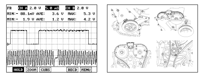
Check that Cam, Crank and Oil pump sprocket timing marks are correctly in alignment

(3)

Monitor these signal waveforms from CAM and Crank shaft position Sensor are correctly in alignment

(4)

Are all timing marks alligned correctly ?

▶ Go to "Check Fuel Pressure Test" as below

(5)

▶ Repair or readjust as necessary and go to "Verification of Vehicle Repair" procedure

6.

Check Fuel Pressure Test

(1)

Refer to "Fuel pressure test" in "Fuel delivery system"

(2)

Are the measured fuel pressure within specifications ?

▶ Substitute with a known - good PCM and check for proper operation. If the problem is corrected, replace PCM and go to "Verification of Vehicle Repair" procedure.

note

There is a memory reset function on scantool that can erase optional parts automatically detected and memorized by PCM. After testing PCM on the vehicle, use this function to reuse the PCM on the others

▶ Repair or replace as necessary above and then, go to " Verification of Vehicle Repair"procedure.

VERIFICATION OF VEHICLE REPAIR

After a repair, it is essential to verify that the fault has been corrected.

1.

Monitor and record the Freeze Frame Data for the Diagnostic Trouble Code(DTC) which has been diagnosed.

2.

Using a Scantool, Clear the DTCs

3.

Operate the vehicle within conditions noted in the freeze frame data or enable conditions

4.

Monitor that all rediness test have been verified as " Complete "

5.

Are any DTCs present ?

▶ Go to the applicable troubleshoooting procedure.

▶ System is performing to specification at this time.

Яндекс.Метрика