

The Mass Air Flow Sensor (MAFS) is located between the air cleaner assembly and the throttle body. The MAFS uses a hot film type sensing element to measure the mass of intake air entering the engine. This hot film type air flow sensor consists of a hot film sensor, housing and metering ducts. Mass air flow rate is measured by detection of heat transfer from a hot film probe. The change in air flow rate causes change in the amount of heat being transferred from the hot film probe surface to the air. A large amount of intake air represents acceleration or high load conditions while a small amount of intake air represents deceleration or idle. The mass of intake air should increase at acceleration and be stable during constant engine speed. The ECM uses this information to determine the injection duration and ignition timing for the desired air/fuel ratio.
The difference between values coming from the MAF Sensor and those are calculated is analyzed. This difference, or error, is then compared to high and low limit calibration values, which are functions of engine speed. ECM compares the difference between MAFS output and calculated flow rate value while enable condition is met.
If the acutal air flow is higher or lower than calculated value(threshold) for more than 2min.
ECM determines that a fault exists and a DTC is stored.
MIL(Malfunction Indicatin Lamp) turns on when the malfunction lasts till consecutive 2 driving cycle.
Item | Detecting Condition | Possible Cause |
DTC Strategy |
•
The MAF Rationality Diagnostic compares the difference between MAF Sensor output and calculated flow rate value to a calibration value | 1. Clogged air cleaner 2. MAFS |
Enable Conditions |
•
Engine Coolant Temperature ≥ 60℃ (Fully Warmed up state)
•
600rpm < Engine Speed < 3000rpm | |
Threshold value |
•
Acutal Air Mass Value is higher or lower than calculated value | |
Diagnosis Time |
•
Continuous (within 2min.) | |
MIL On Condition |
•
2 Driving Cycles |
Air Flow(kg/h) | Frequency(Hz) |
12.6 | 2617 |
18 | 2958 |
23.4 | 3241 |
32.4 | 3653 |
43.2 | 4024 |
57.6 | 4399 |
72 | 4704 |
108 | 5329 |
144 | 5897 |
198 | 6553 |
270 | 7240 |
360 | 7957 |
486 | 8738 |
666 | 9644 |
900 | 10590 |
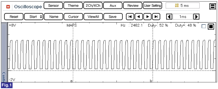
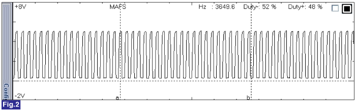


Fig.1) Normal waveform of MAFS at idle. (600rpm & 11kg/h)
Fig.2) Normal waveform of MAFS at acceleration. (2080rpm & 34kg/h)
Fig.3) Normal data of MAFS at idle.
Fig.4) Normal data of MAFS at acceleration.
Fig.5) Abnormal data of MAFS at open or short condition.