IG "OFF" and install a scantool.
Connect probe to APS1 and APS2 to check signal waveform by using oscilloscope function.
Measure signal waveform of APS by pressing and depressing accellerator pedal.
Specification : Signal waveform will be displayed as follows.
Pedal Position | Output Voltage(V) [Vref = 5.0V] | |
APS1 | APS2 | |
C.T | 0.7 ~ 0.8V | 0.29 ~ 0.46V |
W.O.T | 3.85 ~ 4.35V | 1.93 ~ 2.18V |
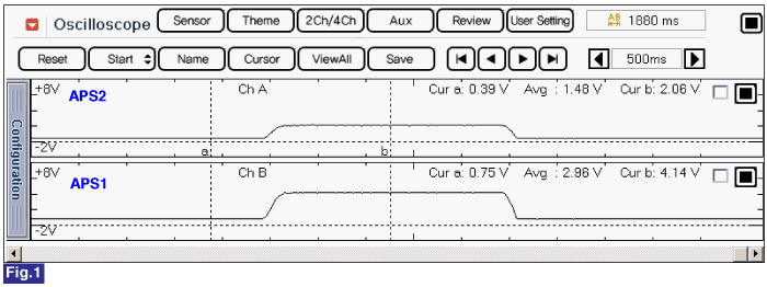
Fig.1) Normal waveform of APS1 & APS2 with acceleration
Is the measured resistance within specification ?
![]() | ▶ Substitute with a known - good ECM and check for proper operation. If the problem is corrected, replace ECM and go to "Verification of Vehicle Repair" procedure. note There is a memory reset function on scantool that can erase optional parts automatically detected and memorized by ECM. Before or after testing ECM on the vehicle, use this function to reuse the ECM on the others |
![]() | ▶ Substitute with a known-good APS and check for proper operation. If the problem is corrected, replace APS and then go to "Verification of Vehicle Repair" procedure. |