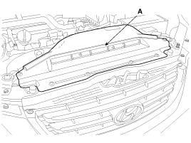
Remove the air duct(A).
Disconnect the battery nagative terminal from the battery.
Remove the air duct(A).

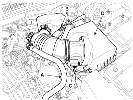
Remove the air cleaner assembly.
Disconnect the breather hose (A).
Disconnect the ECM connectors (B).
Disconnect the AFS connector (C) and then remove the air cleaner assembly (D).
Tightening torque
7.8 ~ 9.8N.m (0.8 ~ 1.0kgf.m, 5.8 ~ 7.2lb-ft)
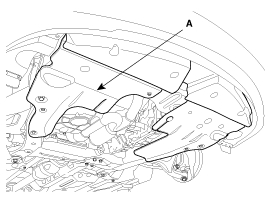
Remove the under cover (A).
Tightening torque
9.8 ~ 11.8N.m (1.0 ~ 1.2kgf.m, 7.2 ~ 8.7lb-ft)
Drain the engine coolant.
Remove the radiator cap to speed draining.
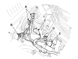
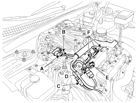
Remove the engine wiring connectors, the harness protetors ans mounting clamps.
RH front, rear oxygen sensor connectors (A)
Power steering oil pressure sensor connector (B)
VIS solenoid valve connector (C)
RH exhaust camshaft OCV connector (D)
RH injector connector (E)
Condenser connector (A)
RH ignition coil connector (B)
Knock sensor connector (C)
LH/RH intake camshaft OCV connector (D)
LH exhaust camshaft OCV connector (E)
LH injector connectors (F)
LH ignition coil connectors (A)
LH exhaust CMPS connector (B)
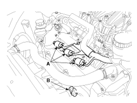
LH front oxygen sensor connector (A)
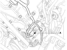
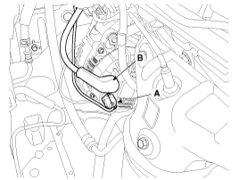
Alternator connector (A) and the 'B' terminal cable (B).
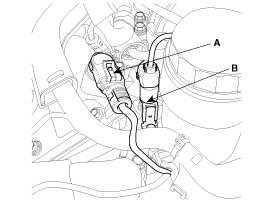
LH intake CMPS connector (A) and the oil pressure switch connector (B)
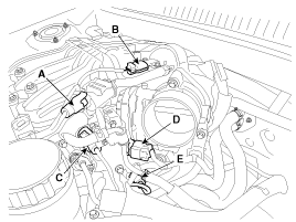
PCSV connector (A)
MAP sensor connector (B)
RH intake CMPS connector (C)
ETC connector (D)
OTS connector (E)
Knock sensor connector (B) and the RH exhaust CMPS connector (A)
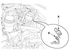
WTS & gauge unit connector (A).
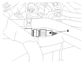
LH rear oxygen sensor connector (A) and the CKPS connector (B)
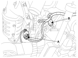
Disconnect the throttle body coolant hoses (A), the brake booster vacuum hose (B) and the fuel hose (C).
Tightening torque :
9.8 ~ 11.8N.m (1.0 ~ 1.2kgf.m, 7.2 ~ 8.7lb-ft)
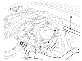
Remove the throttle body (A).
Tightening torque :
9.8 ~ 11.8N.m (1.0 ~ 1.2kgf.m, 7.2 ~ 8.7lb-ft)
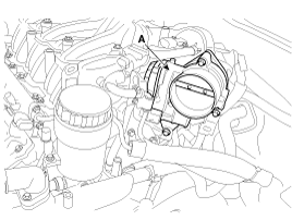
Remove the surge tank stay (A).
Tightening torque
27.5 ~ 31.4N.m (2.8 ~ 3.2kgf.m, 20.3 ~ 23.1lb-ft)
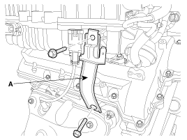
Remove the surge tank (A).
Tightening torque
9.8 ~ 11.8N.m (1.0 ~ 1.2kgf.m, 7.2 ~ 8.7lb-ft)
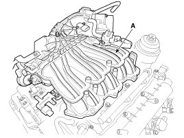
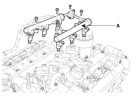
Disconnect the LH injector connectors.
Remove the delivery pipe & injector assembly (A).
Remove the intake the manifold (A).
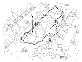
Be sure to drain the engine coolant before removing the intake manifold.
If any coolant drained from the cylinder head vent hole has entered the intake port. This can potentially lead to engine trouble.
Installation is reverse order of removal.
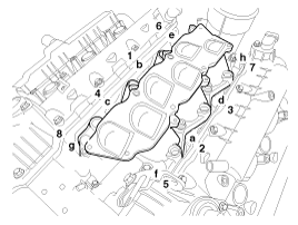
Tighten the intake manifold bolts and nuts, in several passes as below.
Tightening torque
Step 1: 3.9 ~ 5.9N.m (0.4 ~ 0.6kgf.m, 2.9 ~ 4.3lb-ft)
Step 2:Nut- 18.6 ~ 23.5N.m (1.9~2.4kgf.m, 13.7~17.4lb-ft)
Bolt -26.5 ~ 31.4N.m (2.7~3.2kgf.m, 19.5~23.1lb-ft)
Step 3: Repeat 2nd step twice or more.
a ~ h : 1st step order
1 ~ 8 : 2nd step order
Confirm the manifold gasket identification mark (LH, RH) and be careful of the installation direction.
