3.
Is the problem found?

▶ Repair the trouble causing part and go to "Verification of Vehicle Repair".

▶ Go to "Power Circuit Inspection".
ECM is activated by power supply. Signals from several sensors, such as CKPS and APS, is inputted to ECM. Comparing inputted siganals with control LOGIC saved at micro controller and EEPROM, ECM controlls engine as actuating injectors, solenoids and relays. To guarantee accurate control, ECM performs SELF TEST, DIAGNOSIS of several sensors and actuators. And if serious trouble which affects vehicle performance occurrs, ECM sets DTCs.At certain cases, ECM shuts down whole systems in order to prevent dangerous situation due to incorrect control.
P0698 is set when the voltage below 4700mV - minimum voltage of sensor power supply 3 generates from ECM - is detected for more than 0.1 sec. This code is due to the short to ground in sensor power circuit or the voltage problem inside of ECM.
Item | Detecting Condition | Possible Cause | ||
DTC Strategy | ● Voltage monitoring | ● A/C pressure transducer power supply circuit ● DPS power supply circuit ● VSCA power supply circuit ● ECTS signal circuit ● ECM component | ||
Enable Conditions | ● IG KEY "ON" | |||
Threshold Value | ● when the voltage is below the minimum voltage of sensor power supply ( below 4700mV ) | |||
Diagnostic Time | ● 100ms | |||
Fail Safe | Fuel cut | NO | ● Limp home mode is activated (engine speed is fixed at 1200RPM ) | |
EGR Off | NO | |||
Fuel Limit | YES | |||
Check Lamp | NO | |||
※ According to the engine coolant temperature, ECTS signal will vary from 0.6V to 4.5V, therefore, check the voltage after disconnecting connector.
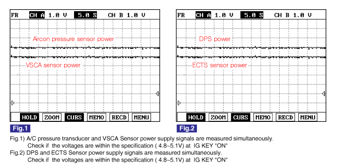
Sensor power 1 | Sensor power 2 | Sensor power 3 |
APS1 CMPS 4830mV~5158mV | RPS, APS 2, BPS, MAFS 4830mV~5158mV | APT, VSCA DPS, ECTS 4830mV~5158mV |
Electrical systems consist of a lot of harness and connectors, poor connection of terminals can cause various problems and damge of component.
Perform checking procedure as follows.
Check damage of harness and terminals : Check terminals for contact resistance, corrosion and deformation.
Check connecting condition of ECM and component connector : Check terminal seperation, damage of locking device and connecting condition between terminal and wiring.
Disconnect the pin which requires checking at male connector and insert it to the terminal at female connector for checking connecting condition. ( after checking, reconnect the pin at correct position. )
Is the problem found?
▶ Repair the trouble causing part and go to "Verification of Vehicle Repair".
▶ Go to "Power Circuit Inspection".
Check power circuit voltage
IG KEY "OFF", ENGINE "OFF"
Disconnector APTS connector, VSCA connector, DPS connector, ECTS connector.
IG KEY "ON"
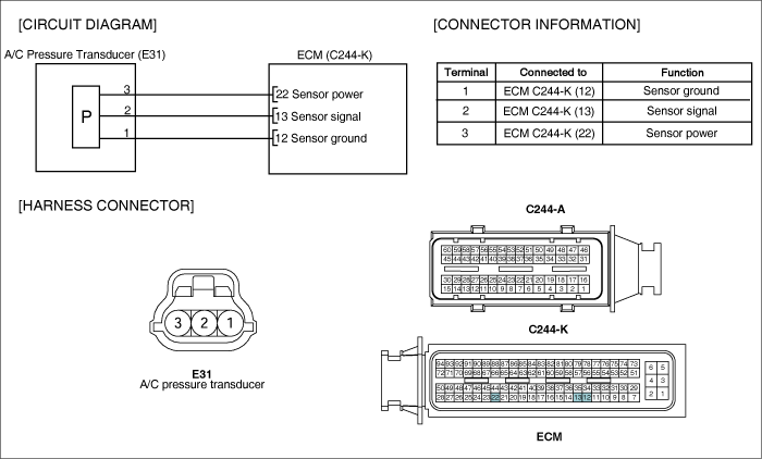
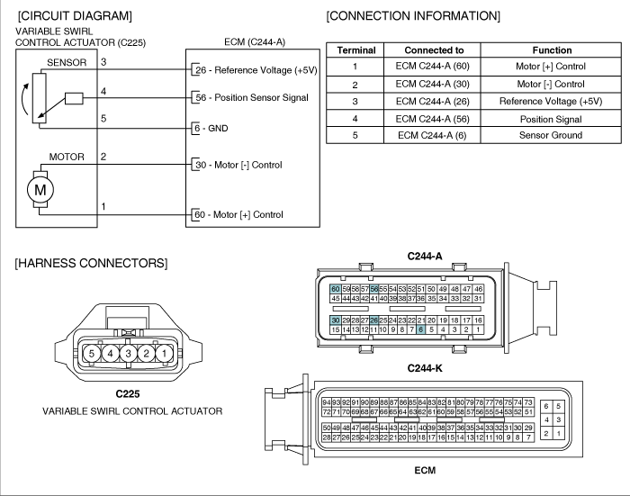
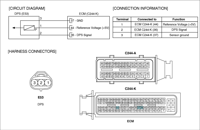
Measure the voltage of APTS connector terminal 3, VSCA connector terminal 3, DPS connector terminal 1 and ECTS terminal 1.
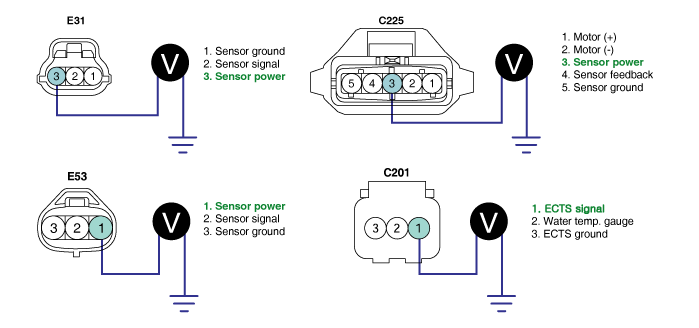
specification : 4.8V~5.1V
Is the measured voltage within the specification?
▶ Go to "Component Inspection".
▶ Go to "2. Check short to ground in power circuit" as follows.
Check short to ground in power circuit
IG KEY "OFF", ENGINE "OFF"
Disconnector APTS connector, VSCA connector, DPS connector, ECTS connector, ECM connectors.
Check continuity between APTS connector terminal 3, VSCA connector terminal 3, DPS connector terminal 1, ECTS connector terminal 1and chassis ground.
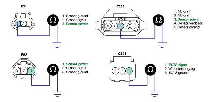
specification : Discontinuity ( Infinite Ω )
Is the measured resistance within the specification?
▶ If the circuit is insulated well and the sensor power supply from ECM is low, replace ECM and go to "Verification of Vehicle Repair".
▶ Repair short to ground and go to "Verification of Vehicle Repair".
IG KEY "OFF", ENGINE "OFF".
Disconnect APTS connector, VSCA connector, DPS connector, ECTS connector.
Check that sensor connector power supply is within the specification after turning IG KEY "ON".
Connect APTS connector and VSCA connector, DPS connector, ECTS connector in turn.
Measure the voltage of power circuit of each sensor with all connector connected.
Specification : APTS, VSCA, DPS : sensor power supply should not change as connecting APTS connector, VSCA connector, DPS connector.
( If the change of sensor power supply occur as connecting sensor connector, this means the occurrence of short inside of sensor.)
ECTS : Connecting ECTS connector terminal, signal voltage is outputted from 0.6V to 4.5V depending on ECTS tempt.
(While connector is being connected, if output voltage rises or no DTC is outputted, the sensor component is considered as normal one.)
Does change of sensor power supply occur as connecting sensor connector?
▶ Replace related sensors.(APTS, VSCA, DPS, ECTS)
▶ Go to "Verification of Vehicle Repair".
After a repair, it is essential to verify that the fault is corrected.
After connecting Scantool select "DIAGNOSTIC TROUBLE CODES(DTCs)" mode.
Clear recorded DTC using Scantool.
Drive the vehicle within DTC "Enable conditions" in "General information".
After selecting "DIAGNOSTIC TROUBLE CODES(DTCs)" mode and check if DTC is recorded again.
Are any DTCs recorded ?
▶ Go to the DTC guide of recorded NO. in Scantool.
▶ System operates within specification.
