4.
IG KEY "ON" after connecting only AFLS ECU to CAN BUS.
(IG KEY "ON" after connecting only "the Control Module(s) to be checked" to CAN BUS.)
Specification
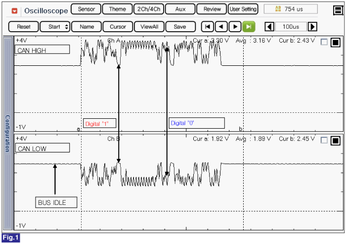
Fig.1) CAN LOW and CAN HIGH Commnication Waveform
Ignition "OFF
Disconnect CAN communication modules.(TCM, ECM, ECS, ABS/ESP/TCS,SAS/EPS, SRS, EPB, Cluster, LKAS, SMK ,SPAS, FATC, AAF, TPMS)
Connect 2 channel scope to DLC CAN HIGH terminal and CAN LOW termina.
IG KEY "ON" after connecting only AFLS ECU to CAN BUS.
(IG KEY "ON" after connecting only "the Control Module(s) to be checked" to CAN BUS.)
Fig.1) CAN LOW and CAN HIGH Commnication Waveform
Does correct waveform generate from each module?
 | ▶ Replace the module which generates poor communication waveform, and go to "Verification of Vehicle Repair". |
 | ▶ Fault is intermittent caused by poor contact in the sensor’s and/or AFLS ECU’s connector or was repaired and AFLS ECU memory was not cleared. Thoroughly check connectors for looseness, poor connection, bending, corrosion, contamination, deterioration, or damage. Repair or replace as necessary and go to "Verification of vehicle Repair" procedure. |
