
This is DTC which is related with communication error between BCM and other units.
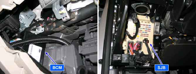
※ Body CAN communication Control Units : BCM(Body Control Module), CLU(Cluster), PSM(Power Seat Module), SMK(Smart Key), SJB(Smart Junction Box), PTM(Power Tail gate Module).
*¹ CAN (Controller Area Network) : CAN is serial bus communication type which links not only communication system but also control units each other.
This is DTC which is related with communication error between BCM and other units.
(※ Control Units : BCM(Body Control Module), CLU(Cluster), PSM(Power Seat Module), SMK(Smart Key), SJB(Smart Junction Box), PTM(Power Tail gate Module)
Case1: After short between CLU CAN Low Line and High Line, short to ground together.
Case2: After short between CLU CAN Low Line and High Line, short to power together.
※ This code is occurred when It is not possible to transmit data by CAN Line in those way of Software and Hardware. But, It is possible to receive data by CAN Line.
This code reports BUS OFF status when data transmit error count number is over 255. The purpose is to verify the status of CAN controller and CAN communication line when error is detected.
According to operation condition, some of module which are connected to CAN line may not detect B1603.
Also, B1602 coincides with B1603 at all times.
Difference between CAN ERROR and CAN BUS ERROR
CAN Error : MIL On, CAN Bus Error : No MIL
Item | Detecting Condition | Possible Cause |
DTC Strategy |
•
CAN Communication Check | 1. BCM are not Sleep condition (1) CAN High and Low Line short to ground coincident (2) CAN High and Low Line short to battery coincident |
Enable Conditions |
•
BCM power on | |
Threshold Value |
•
CAN High/Low : 0V or B+ | |
Diagnostic Time |
•
More than 10ms | |
DTC Erasing Time |
•
DTC is erased immediately after trouble fixed |
Fig.1) CAN Low/High Signal Waveform
Fig.2) CAN BUS VOLTAGE LEVEL (LOW SPEED CAN)