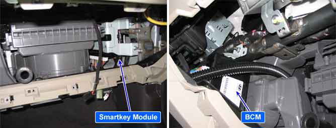
Body electrical system is consist of 6 Units BCM(Body Control Module), PSM(Power Seat Module), PTM(Power tail gate), SJB(Smart Junction Box), SMK(Smart Key Control Module), CLU(Cluster) constructing the Body Wiring system is connected to BODY CAN*¹.
*¹ CAN (Controller Area Network): CAN is serial bus communication type which links not only communication system but also control units each other.
It is impossible to communication via CAN.
As the CAN Communication error, it is occurred to the battery shorted or the ground shorted for CAN high & Low.
and then it is set The DTC of “CAN BUS off”. It is used to validate wire errors.
To distinguish CAN error and CAN BUS off, During operating RKE Lock/Unlock of Fob key, the CAN error is set but CAN BUS off is not set.
Item | Detecting Condition | Possible Cause |
DTC Strategy |
•
To check CAN Communication status | 1. The contact state for connector 2. Input power for smart key unit. (PIC IMMO) 3. In the driver door open status ( It is not SMK sleep mode), Check the battery short or ground short for CAN High & Low 4. Smart key Unit (PIC UNIT) |
Enable Conditions |
•
At the state of input battery voltage into a SMK 1. CAN High&Low Battery Short 2. CAN Hogh&Low Ground Short | |
Threshold value |
•
CAN High&Low : Battery short : the voltage is 12V. Ground short : the voltage is 0V. | |
Diagnostic Time |
•
After occurring DTC, it is detected immediately | |
DTC Erasing Time |
•
After solving fault, DTC is deleted immediately |