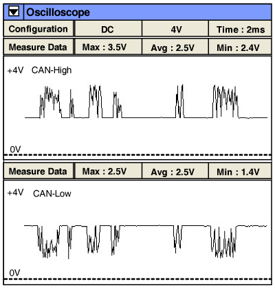

CAN communication consists of CAN low line, CAN high line and two resister. The resister are installed in Cluster and PCM/ECM. The CAN system allow communication between control module(PCM/ECM, MDPS, FATC, ABS)
DTC C1616 is set when TPMS ECU detects CAN communication error.
Item | Detecting Condition | Possible cause |
DTC Strategy |
•
CAN Signal Check | 1. Poor connection 2. Power supply to each Module 3. Open or short in PCM/ECM communication line 4. Open or short in TPMS ECU communication line 5. 120Ω register( Inside cluster) 6. PCM/ECM |
Enable Conditions |
•
IG ON | |
Threshold value |
•
Failure on CAN communication line for more than 5 sec |
