
Several control units are applied to electronically controlled vehicles. These units perform each control with informations from various sensors. Thus, sharing signal information from sensors is needed, so CAN communication type whose communication speed is high and insensitive to electrical noise by spark generation is adopted to controlling power-train(engine, atutomatic transaxle, ABS, TCS, ECS)AFLS ECU is input some informations(engine speed, steering angle sensor's signal, vehicle speed) in order to maintain optimum headlamp condition through CAN communication. AFLS ECU determine range performance to headlamp in according with brake switch signal When critical braking.
AFLS ECU set this code If input value(brake switch signal) is message signal timeout or invalid value.
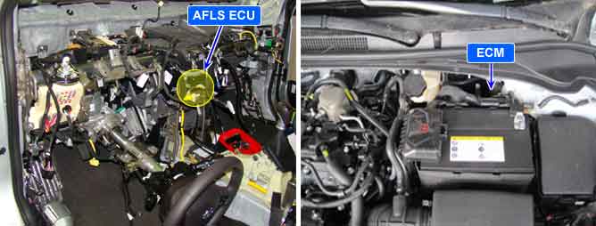
Item | Detecting Condition | Possible Cause |
DTC Strategy |
•
Signal monitoring | 1. CAN communication circuit Open/Short 2. Brake S/W circuit Open/Short 3. Faulty ECM |
Enable Conditions |
•
IG ON | |
Threshold Value |
•
Brake S/W output is invalid value. CAN communication signal not output from Engine ECU | |
Detecting time |
•
1sec. | |
Fail Safe |
•
Leveling : performance decline. Swivelling : normal operation. | |
Check Lamp |
•
NO |