
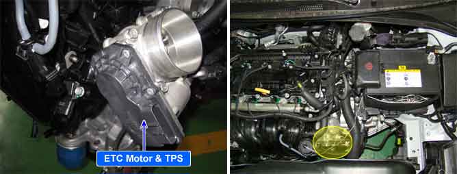
The Electronic Throttle Control(ETC) system consists of the throttle body, Throttle Position Sensor(TPS)1&2 and Accelerator Position Sensor(APS) 1&2. TPS1&2 are sharing the same source voltage and ground. The throttle valve opening is control by throttle motor which is controlled by Engine Control Module(PCM). The opposite position indicator shows inverted signal characteristics. TPS1 output voltage increases smoothly in proportion with the throttle valve opening angle after starting. TPS2 output voltage decreases in inverse proportion with the throttle valve opening angle after starting. TPS provides feedback to the PCM to control the throttle motor in order to control the throttle valve opening angle properly in response to the driving condition.
PCM sets DTC P0123 if the PCM detects signal voltage higher than the possible range of a properly operating TPS1.
Item | Detecting Condition | Possible Cause | |
DTC Strategy |
•
Short to Battery or Open circuit | 1. Open in ground circuit 2. Short to battery in signal circuit 3. Poor connection or damaged harness 4. Faulty TPS1 | |
Case1 | Enable Conditions |
•
Ignition "ON" | |
Threshold Value |
•
TPS > 4.9V | ||
Case1 | Enable Conditions |
•
Ignition "ON"
•
In idle status
•
Target throttle angle < 58%
•
MAF Limphome detected or TPS2 failure detected | |
Threshold Value |
•
TPS1 > 3.0V | ||
Diagnostic Time |
•
0.05 sec. | ||
Mil On Condition |
•
1 Driving Cycles | ||
Limp-Home |
•
Forced limited power mode : When the DTC is set, the PCM reduces engine torque by 25% of normal value.
•
The PCM uses TPS2 signal to monitor the controlled opening angle of the throttle valve. | ||