
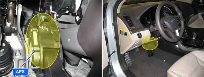
The APS is a very important sensor which controls the fuel amount by transmitting the driver's accelerating intention to ECM/PCM. And it is divided into APS 1,2 because its reliability is important. The APS 1,2 are composed with the independent power and ground. APS 2 shows the 1/2 output of the APS1 and decides the fault if the ratio of APS 1,2 is different. When the APS 1 is out of order, the signal of APS 2 can be substituted instead of APS 1 and vise versa.
Checking output signals from APS 1 and 2 under detecting condition, if output signals difference between APS 1 and 2 are detected more than 4.5% for the specified number of times., ECM/PCM sets P2138.
Item | Detecting Condition | Possible Cause |
DTC Strategy |
•
Plausibility check between pedal value sensor 1, 2 | 1. Poor connection 2. Open or short in APS circuit 3. Faulty APS 4. Faulty ECM/PCM |
Enable Conditions |
•
IG ON | |
Threshold Value |
•
I (APS1/2) –APS2 I > Threshold f(Eng. rpm) | |
Diagnostic Time |
•
0.25 sec | |
MIL ON Condition |
•
Immediately |
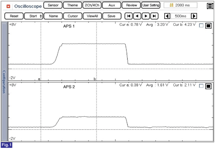
Fig.1) Normal waveform of APS1 & APS2 with acceleration
Signal waveform of APS 1 & 2 shows that APS 2 increases voltage just half of APS 1 voltage increase when accelerating.