
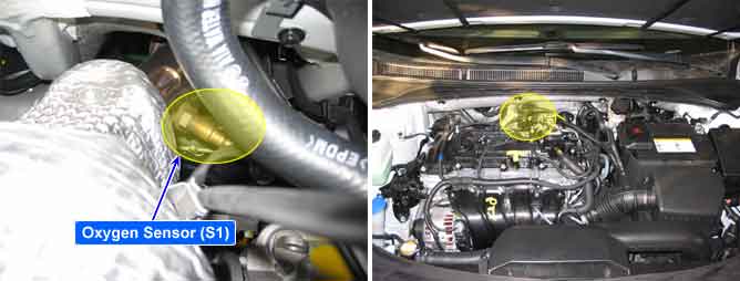
Lambda sensor installed at exhaust manifold is planar ZrO2 dual cell type and it senses O2 density of exhaust gas for accurate EGR control through fuel correction. It also limits smoke which is generated by reach air-fuel mixture at engine maximum loading condition. ECM/PCM controls pumping current in order to fit λ-value from linear O2 sensor to 1.0.
Lean air-fuel mixture(1.0<λ<1.1) : ECM/PCM supplies pumping current to Lambda sensor (+pumping current) and activates it for Lambda sensor to have the characteristic at λ=1.0 (0.0 pumping current). With the value of pumping current supplied to Lambda sensor, ECM/PCM detects O2 density of exhaust gas.
Rich air-fuel mixture(0.9<λ<1.0) : ECM/PCM takes away pumping current from O2 sensor (-pumping current) and deactivates it for Lambda sensor to have the characteristic at λ=1.0 (0.0 pumping current). With the value of pumping current taken away from Lambda sensor, ECM/PCM detects O2 density of exhaust gas.
This performance is the most active and fast at normal operating temp.(450℃~600℃) thus, in order to reach normal operating temp. and last at that temp., heater(heating coil) is integrated with Lambda sensor.
Heater coil is controlled by ECM/PCM as PWM. the resistance of heater coil is low when coil is cold thus, current through it increases while resistance is high when coil is hot thus, current decreases. With this principle, Lambda sensor temp. is measured and Lambda sensor heater operation varies based on the data.
If ECM/PCM detects that the output signal satisfies the threshold values under enable conditions, ECM/PCM sets DTC P0130.
(This DTC might be caused by the malfunction of Heater circuit, so, check the heater circuit first.)
Item | Detecting Condition | Possible Cause | |
DTC Strategy |
•
Rationality check | 1. Poor connection 2. Open or short power/ground in signal circuit 3. S1 | |
General Enable Conditions |
•
Dew point end detected
•
Fuel feed back control active
•
Battery voltage > 11V
•
Exhaust Gas temperature = 536℉~1472℉
•
No injector error
•
No upstream O2 sensor heater error | ||
Case1 | Enable Conditions |
•
S2 sensor voltage > 0.5V | |
ThresholdValue |
•
S1 sensor voltage : 0.06 ~ 0.4V | ||
DiagnosticTime |
•
25 sec | ||
Case2 | Enable Conditions |
•
S2 sensor voltage < 0.1V | |
ThresholdValue |
•
S1 sensor voltage : 0.6 ~ 1.08V | ||
DiagnosticTime |
•
10 sec | ||
Case3 | Enable Conditions |
•
Time after dew point end detected > 10s | |
ThresholdValue |
•
Counter of l ∆usvk > 2V during 0.04 sec after heater on→off l ≥ 5 times | ||
MIL ON Condition |
•
2 driving cycle | ||
※ ∆usvk : Sum of the signal voltage change value (S1)
※ S1 : upstream oxygen sensor / S2 : downstream oxygen sensor
Waveform of sensor Current Pump at IG KEY "ON" and Engine running. It fluctuates between 2V and 3V periodically.
Waveform of sensor Vertual Ground Output at IG KEY "ON" and Engine running. 2.5V is displayed.
Waveform of sensor Current Adjust at IG KEY "ON" and Engine running. It fluctuates between 2V and 3V periodically. Waveform of sensor Nernst Voltage at IG KEY "ON" and Engine running. 2.9V is displayed.