3.
Is the problem found?
 | ▶ Repair the trouble causing part and go to "Verification of Vehicle Repair". |
 | ▶ Go to "Power Circuit Inspection". |
Electrical systems consist of a lot of harness and connectors, poor connection of terminals can cause various problems and damge of component.
Perform checking procedure as follows.
Check damage of harness and terminals : Check terminals for contact resistance, corrosion and deformation.
Check connecting condition of ECM and component connector : Check terminal seperation, damage of locking device and connecting condition between terminal and wiring.
Disconnect the pin which requires checking at male connector and insert it to the terminal at female connector for checking connecting condition. ( after checking, reconnect the pin at correct position. )
Is the problem found?
| ▶ Repair the trouble causing part and go to "Verification of Vehicle Repair". |
| ▶ Go to "Power Circuit Inspection". |
IG KEY "OFF", ENGINE "OFF".
Disconnect APS connector.
IG KEY "ON".
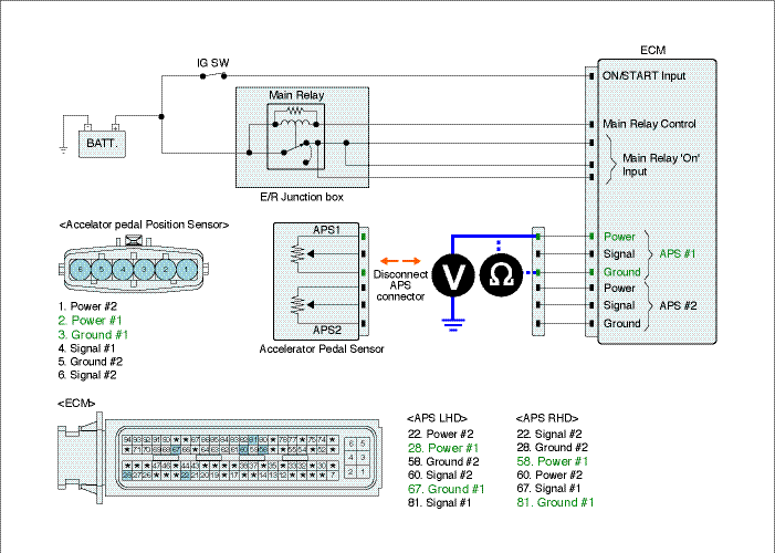
Measure the voltage between power terminal of APS1 harness connector and chassis ground.
Measure the voltage between power terminal of APS2 harness connector and chassis ground.
Specification : 4.8V~5.1V
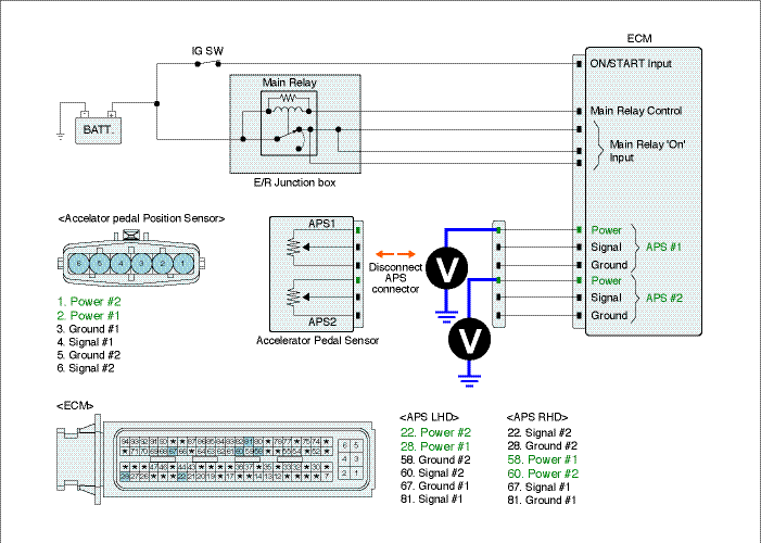
Is the measured voltage within the specification?
| ▶ Go to "Signal Circuit Inspection". |
| ▶ If the measured voltage is not within the specified value, find and repair trouble causing part in circuits and go to "Verification of Vehicle Repair". When the measured voltage is higher than the specified value : Refer to P0643 Circuit Inspection. (APS1) Refer to P0653 Circuit Inspection.(APS2) When the measured voltage is lower than the specified value : Refer to P0642 Circuit Inspection.(APS1) Refer to P0652 Circuit Inspection.(APS2) |
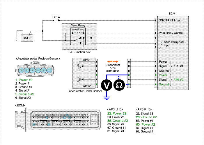
Check open in signal circuit
IG KEY "OFF", ENGINE "OFF".
Disconnect APS connector and ECM connector.
Check continuity between signal terminal of APS1 harness connector and signal terminal of ECM harness connector.(APS1)
Check continuity between signal terminal of APS2 harness connector and signal terminal of ECM harness connector.(APS2)
Specification : Continuity (below 1.0Ω)
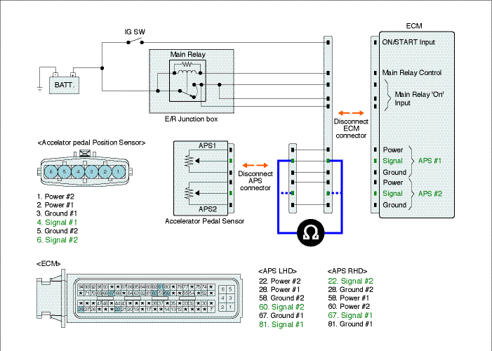
Is the measured resistance within the specification?
| ▶ Go to "Check short in signal circuit". |
| ▶ Repair open in signal circuit and go to "Verification of Vehicle Repair". |
Check short in signal circuit ( APS 1 )
IG KEY "OFF", ENGINE "OFF".
Disconnect APS connector and ECM connector.
IG KEY "ON".
Check continuity between signal terminal of APS1 harness connector and chassis ground. (Check short to ground )
Measure the voltage between signal terminal of APS1 harness connector and chassis ground. (Check short to battery )
Specification : Check short to ground : Discontinuity ( Infinite Ω )
Check short to battery : 0.0V~0.1V
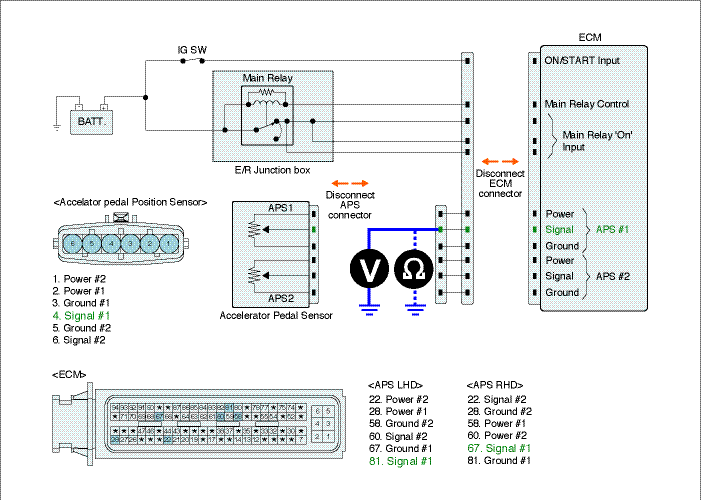
Is APS 1 signal circuit insulated normally?
| ▶ Go to "3.Signal Circuit Inspection (APS 2)" as follows. |
| ▶ Repair short in circuit and go to "Verification of Vehicle Repair". |
Signal Circuit Inspection (APS 2)
IG KEY "OFF", ENGINE "OFF".
Disconnect APS connector and ECM connector.
IG KEY "ON".
Check continuity between signal terminal of APS2 harness connector and chassis ground. (Check short to ground )
Measure the voltage between signal terminal of APS2 harness connector and chassis ground. (Check short to battery )
Specification : Check short to ground : Discontinuity ( Infinite Ω )
Check short to battery : 0.0V~0.1V
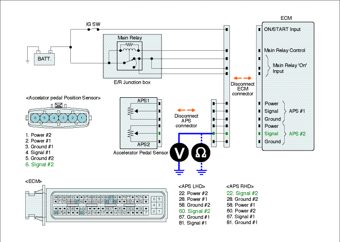
Is APS 2 signal circuit insulated normally?
| ▶ Go to "Ground Circuit Inspection". |
| ▶ Repair short in circuit and go to "Verification of Vehicle Repair". |
Check ground circuit (APS1)
IG KEY "OFF", ENGINE "OFF".
Disconnect APS connector.
IG KEY "ON".
Measure the voltage between power terminal of APS1 harness connector and chassis ground. [ TEST "A" ]
Measure the voltage between power terminal and ground terminal of APS1 harness connector. [ TEST "B" ]
( Power terminal : Check + prove , Ground terminal 4 : Check - prove )
Specification : [TEST "A"] Voltage - [TEST "B"] Voltage = below 200mV
Is the measured voltage within the specification?
| ▶ Go to "2. Check ground circuit (APS2)". |
| ▶ When "B" voltage is not detected : Repair open in ground circuit and go to "Verification of Vehicle Repair". ▶ When the voltage difference between "A" and "B" is above 200mV : Eliminate the causes of excessive resistance and go to "Verification of Vehicle Repair". |
Check ground circuit (APS2)
IG KEY "OFF", ENGINE "OFF".
Disconnect APS connector.
IG KEY "ON".
Measure the voltage of APS terminal 6. [ TEST "A" ]
Measure the voltage of APS terminal 6 and terminal 2. [ TEST "B" ]
( terminal 6: Check + prove , terminal 2 : Check - prove )
Specification : [TEST "A"] Voltage - [TEST "B"] Voltage = below 200mV
Is the measured voltage within the specification?
| ▶ Go to "Component Inspection". |
| ▶ When "B" voltage is not detected : Repair open in ground circuit and go to "Verification of Vehicle Repair". ▶ When the voltage difference between "A" and "B" is above 200mV : Eliminate the causes of excessive resistance and go to "Verification of Vehicle Repair". |
