3.
Is the problem found?
 | ▶ Repair the trouble causing part and go to "Verification of Vehicle Repair". |
 | ▶ Go to "Power Circuit Inspection". |
Electrical systems consist of a lot of harness and connectors, poor connection of terminals can cause various problems and damge of component.
Perform checking procedure as follows.
Check damage of harness and terminals : Check terminals for contact resistance, corrosion and deformation.
Check connecting condition of ECM and component connector : Check terminal seperation, damage of locking device and connecting condition between terminal and wiring.
Disconnect the pin which requires checking at male connector and insert it to the terminal at female connector for checking connecting condition. ( after checking, reconnect the pin at correct position. )
Is the problem found?
| ▶ Repair the trouble causing part and go to "Verification of Vehicle Repair". |
| ▶ Go to "Power Circuit Inspection". |
Check brake switch 1 "HOT AT ALL TIMES"
IG KEY "OFF", ENGINE "OFF".
Disconnect brake switch connector.
Measure the voltage between power input terminal of brake switch 1 harness connector and chassis ground.
Secification : 11.5V~13.0V
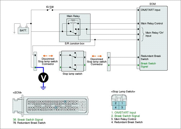
Is the measured voltage within the specification?
| ▶ Go to "2.Check brake switch 2 main relay power" as follows. |
| ▶ Repair STOP FUSE in I/P JUNCTION BOX and related circuit and go to "Verification of Vehicle Repair". |
Check brake switch 2 main relay power
IG KEY "OFF", ENGINE "OFF".
Disconnect brake switch connector.
IG KEY "ON".
Measure the voltage between power terminal of brake switch 2 harness connector and chassis ground.
Specification : 11.5V~13.0V
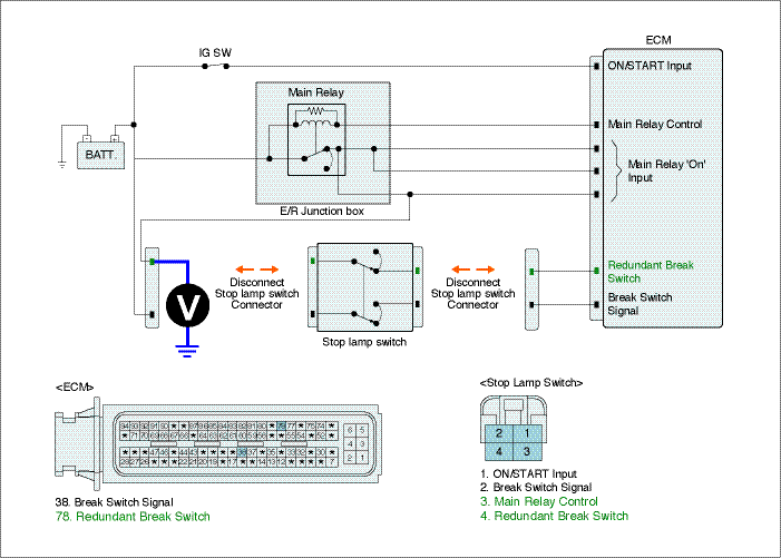
Is the measured voltage within the specification?
| ▶ Go to "Signal Circuit Inspection". |
| ▶ Repair SNSR1 FUSE in E/R JUNCTION BOX and related circuit and go to "Verification of Vehicle Repair". |
Check brake switch signal circuit voltage
IG KEY "OFF", ENGINE "OFF".
Connect brake switch connector and ECM connector.
Measure the voltage of ECM connector terminal 38 and 80 as depressing brake pedal.
Brake Pedal Released | Brake Pedal Depressed | |
Brake Switch Signal | 0.0V~0.1V | 11.5V~13.0V |
Redundant Brake Switch | 11.5V~13.0V | 0.0V~0.1V |
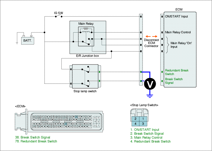
Is the measured voltage within the specification?
| ▶ Go to "Verification of Vehicle Repair". |
| ▶ If component has no problem after performing "Component Inspection" and go to "2. Check open in signal circuit". |
Check open in signal circuit
IG KEY "OFF", ENGINE "OFF".
Disconnect brake switch connector and ECM connector.
Check continuity between brake switch connector terminal 1 and ECM connector(CUD-K) terminal 38. (brake switch 1 circuit)
Check continuity between brake switch connector terminal 4 and ECM connector(CUD-K) terminal 80. (brake switch 2 circuit)
Specification : Continuity ( below 1.0Ω )
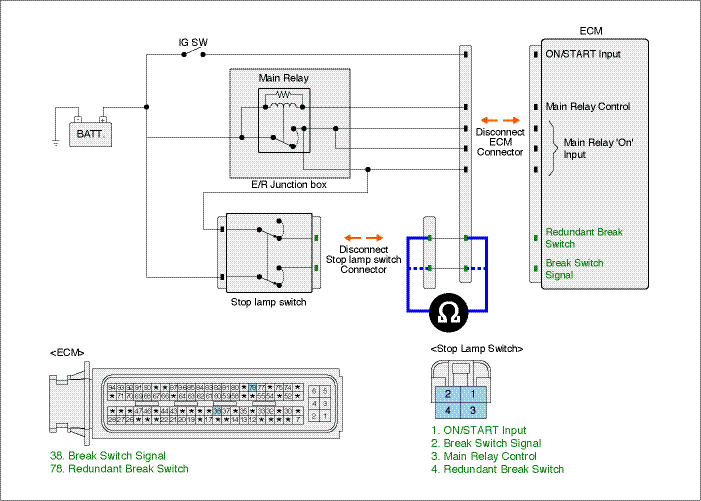
Is the measured resistance within the specification?
| ▶ Repair short in signal circuit and go to "Verification of Vehicle Repair". |
| ▶ Repair open in signal circuit and go to "Verification of Vehicle Repair". |
