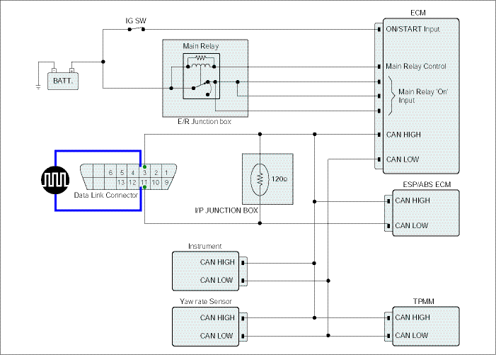
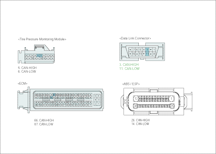
Check CAN communication waveform generation
IG KEY "OFF", ENGINE "OFF".
Disconnect ECM, and ABS(ESP) connector.
Connect 2 channel scope to DLC terminal 3(CAN HIGH) and 11(CAN LOW).
IG KEY "ON" after connecting only "the Control Module(s) to be checked" to CAN BUS.
Specification : At IG KEY "ON", the waveform same as "Signal Waveform & Data" of this code generates.
※ Different from "Signal Waveform & Data", if 1) both CAN HIGH and LOW signal are fixed at 2.5 V or 2) HIGH and LOW signal are fixed at 3.5 V and 1.5 V, respectively, it is due to communication error between modules.


Is there a module which outputs normal waveform after disconnecting module connectors or which outputs abnormal waveform after connecting module connectors?
 | ▶ Replace the module which generates poor communication waveform, and go to "Verification of Vehicle Repair". |
 | ▶ Go to "Verification of Vehicle Repair". |
