
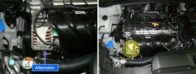
Alternator output and power demand of all electrical loads and systems must be matched to each other as ideally as possible so that the entire system is reliable and trouble-free in operation. The PCM monitors alternator output deviation from the signal of the FR terminal of the alternator when the engine is running.
PCM sets DTC P0625 if the PCM detects output duty signal lower than the possible range of a properly operating alternator.
Item | Detecting Condition | Possible Cause | |
DTC Strategy |
•
Electrical Check | 1. Short to battery in harness 2. Poor connection or damaged harness | |
Enable Conditions | Case1 |
•
Time after ignition ON > 0.1 sec.
•
Engine speed=0
•
No main relay error | |
Case2 |
•
Engine speed > 0rpm
•
No relevant failure
•
Battery voltage < 16V
•
600< Engine speed(rpm) < 4000
•
Coolant temp. > 73℃(140℉) | ||
Threshold Value | Case1 |
•
Alternator load < 15% | |
Case2 |
•
Alternator load < 2% | ||
Diagnostic Time | Case1 |
•
1 sec. | |
Case2 |
•
20 sec. | ||
MIL On Condition |
•
- | ||
① Normal waveform with IG ON
② Normal waveform with Idle and no electrical load
③ Normal waveform with Idle and part electrical load
④ Normal waveform with Idle and full electrical load(A/C, Defrost, Head Lamp, Repeater, Audio, etc)