1.
Self-diagnosis process
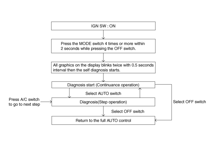
Self-diagnosis process
How to read self-diagnostic code
During the self-diagnosis, the corresponding fault code flickers on the setup temperature display panel every 0.5 second and will show two figures. Fault codes are displayed in numerical format
Display | Fail description |
0 | Normal |
11 | In-car sensor open |
12 | In-car sensor short |
13 | Ambient temperature sensor open |
14 | Ambient temperature sensor short |
17 | Evaporator temperature sensor open |
18 | Evaporator temperature sensor short |
19 | Temperature door potentiometer open/short (Driver) |
20 | Temperature door potentiometer fault (Driver) |
21 | Mode door potentiometer open/short |
22 | Mode door potentiometer fault |
25 | Intake door potentiometer open/short |
26 | Intake door potentiometer fault |
32 | Temperature door potentiometer open/short (Passenger) |
33 | Temperature door potentiometer fault (Passenger) |
43 | Defog door potentiometer open/short |
44 | Defog door potentiometer fault |
45 | APT (A/C Pressure Transducer) CAN signal fault |
47 | RPM CAN signal fault |
48 | Vehicle speed CAN signal fault |
49 | Engine coolant temperature CAN signal fault |
50 | Cluster ionizer fault |
51 | Auto defogging sensor communication and sensor input fault |
Fault code display
Continuance operation: DTC code is none or one.

Continuance operation: DTC code is two or more.

STEP operation
Normal or one fault code is same as a continuance operation.
DTC code is two or more.

If fault codes are displayed during the check, inspect malfunction causes by referring to fault codes.
Fail safe
No | Sensor | Fail condition | Fail safe function |
1 | In-car sensor | < 0.1V or > 4.9V | 23℃ (73.4℉) |
2 | Ambient temperature sensor | < 0.1V or > 4.9V | 20℃ (68℉) |
3 | Evaporator temperature sensor | < 0.1V or > 4.9V | -2℃ (28.4℉) |
4 | Photo sensor | - | No compensation |
5 | Auto defogging sensor (relative humidity) | Communication fail | ● Relative humidity: 60%, ● Surrounding temperature: 23℃ (73.4℉) |
6 | Auto defogging sensor (glass temperature) | < 0.1V or > 4.9V | Glass temperature: 23℃ (73.4℉) |
7 | Temperature control actuator feedback | < 0.1V or > 4.9V | ● Setting temperature is 24.5℃ (76.1℉) or below: Max cool ● Setting temperature is 25.0℃ (77℉) or above: Max hot |
8 | Mode control actuator feedback | < 0.1V or > 4.9V | ● Vent: Vent ● Others: Defog |
9 | Intake actuator feedback | < 0.1V or > 4.9V | ● Recirculation: Recirculation ● Others: Fresh |
10 | Auto defogging actuator feedback | < 0.1V or > 4.0V | ● Close: Close ● Others: Open |
Disconnect the negative (-) battery terminal.
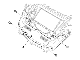
Remove the passenger side crash pad side cover (A).
Remove the crash pad garnish (A) after loosening the mounting screw.
Remove the center facia panel (A) after loosening the mounting screws and then disconnect the connectors and aspirator.
Remove the heater & A/C controller (A) from the center facia after loosening the mounting screws.
Install in the reverse order of removal.
