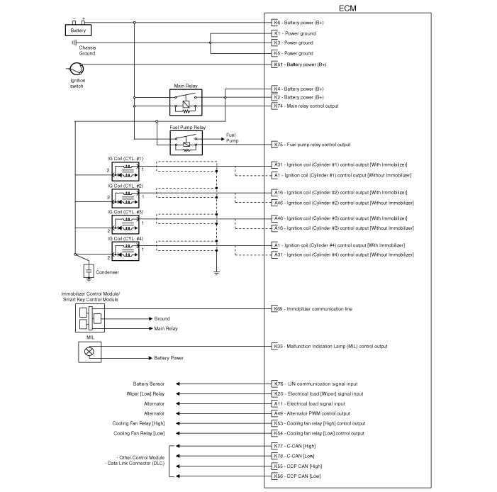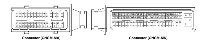
Pin No. | Description | Connected to |
1 | Ignition Coil (Cylinder #1) control output | Ignition Coil (Cylinder #1) [Without Immobilizer] |
Ignition Coil (Cylinder #4) control output | Ignition Coil (Cylinder #4) [With Immobilizer] | |
2 | Injector (Cylinder #1) control output | Injector (Cylinder #1) |
3 | - |
|
4 | Start motor relay control output | Start motor relay |
5 | Heated Oxygen Sensor (HO2S) [Bank 1/Sensor 2] Heater control output | Heated Oxygen Sensor (HO2S) [Bank 1/Sensor 2] |
6 | Sensor ground | Heated Oxygen Sensor (HO2S) [Bank 1/Sensor 2] |
7 | Heated Oxygen Sensor (HO2S) [Bank 1/Sensor 2] signal input | Heated Oxygen Sensor (HO2S) [Bank 1/Sensor 2] |
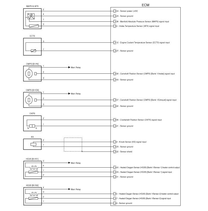
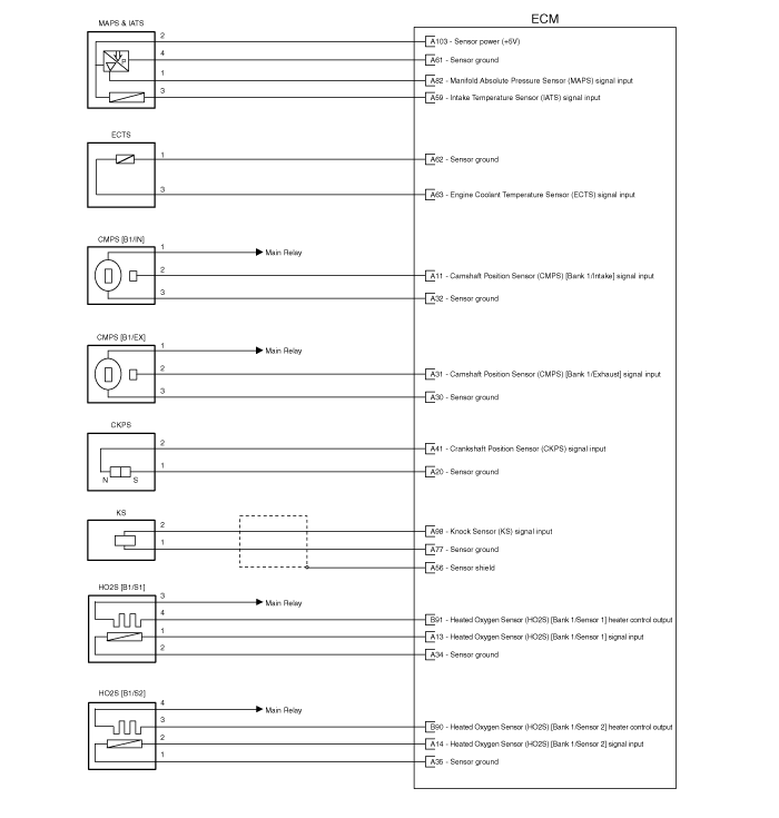
8 | Knock Sensor (KS) signal input | Knock Sensor (KS) |
9 | Intake Air Temperature Sensor (IATS) signal input | Intake Air Temperature Sensor (IATS) |
10 | Start motor contol switch | Start key control module |
11 | Electrical load signal input | Alternator |
12 | Engine Coolant Temperature Sensor (ECTS) signal input | Engine Coolant Temperature Sensor (ECTS) |
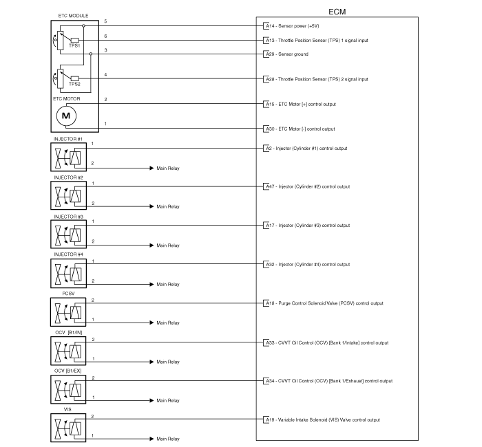
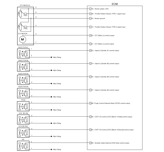
13 | Throttle Position Sensor (TPS) 1 signal input | Throttle Position Sensor (TPS) 1 |
14 | Sensor power (+5V) | Throttle Position Sensor (TPS) 1,2 |
15 | ETC Motor [+] control output | ETC Motor |
16 | Ignition Coil (Cylinder #3) control output | Ignition Coil (Cylinder #3) [Without Immobilizer] |
Ignition Coil (Cylinder #2) control output | Ignition Coil (Cylinder #2) [With Immobilizer] | |
17 | Injector (Cylinder #3) control output | Injector (Cylinder #3) |
18 | Purge Control Solenoid Valve (PCSV) control output | Purge Control Solenoid Valve (PCSV) |
19 | Variable Intake Solenoid (VIS) Valve control output | Variable Intake Solenoid (VIS) Valve |
20 | - |
|
21 | - |
|
22 | Sensor shield ground | Knock Sensor (KS) |
23 | Sensor ground | Knock Sensor (KS) |
24 | Sensor ground | Manifold Absolute Pressure Sensor (MAPS) |
25 | Sensor ground | Battery Sensor |
26 | - |
|
27 | Sensor ground | Engine Coolant Temperature Sensor (ECTS) |
28 | Throttle Position Sensor (TPS) 2 signal input | Throttle Position Sensor (TPS) 2 |
29 | Sensor ground | Throttle Position Sensor (TPS) 1,2 |
30 | ETC Motor [-] control output | ETC Motor |
31 | Ignition Coil (Cylinder #4) control output | Ignition Coil (Cylinder #4) [Without Immobilizer] |
Ignition Coil (Cylinder #1) control output | Ignition Coil (Cylinder #1) [With Immobilizer] | |
32 | Injector (Cylinder #4) control output | Injector (Cylinder #4) |
33 | CVVT Oil Control (OCV) Valve [Bank 1/Intake] control output | CVVT Oil Control Valve (OCV) [Bank 1/Intake] |
34 | CVVT Oil Control (OCV) Valve [Bank 1/Exhaust] control output | CVVT Oil Control Valve (OCV) [Bank 1/Exhaust] |
35 | Sensor power (+5V) | Battery Sensor |
36 | - | |
37 | - | |
38 | - | |
39 | Manifold Absolute Pressure Sensor (MAPS) signal input | Manifold Absolute Pressure Sensor (MAPS) |
40 | Battery Sensor signal | Battery Sensor |
41 | Sensor ground | Crankshaft Position Sensor (CKPS) |
42 | Sensor ground | Camshaft Position Sensor (CMPS) [Bank 1/Exhaust] |
43 | Sensor ground | Camshaft Position Sensor (CMPS) [Bank 1/Intake] |
44 | - | |
45 | - | |
46 | Ignition Coil (Cylinder #2) control output | Ignition Coil (Cylinder #2) [Without Immobilizer] |
Ignition Coil (Cylinder #3) control output | Ignition Coil (Cylinder #3) [With Immobilizer] | |
47 | Injector (Cylinder #2) control output | Injector (Cylinder #2) |
48 | - |
|
49 | Alternator PWM control output | Alternator |
50 | Heated Oxygen Sensor (HO2S) [Bank 1/Sensor 1] Heater control output | Heated Oxygen Sensor (HO2S) [Bank 1/Sensor 1] |
51 | Heated Oxygen Sensor (HO2S) [Bank 1/Sensor 1] signal input | Heated Oxygen Sensor (HO2S) [Bank 1/Sensor 1] |
52 | - | |
53 | Sensor ground | Heated Oxygen Sensor (HO2S) [Bank 1/Sensor 1] |
54 | Sensor power (+5V) | Manifold Absolute Pressure Sensor (MAPS) |
55 | Battery Current Direct input | Battery Sensor |
56 | Crankshaft Position Sensor (CKPS) signal input | Crankshaft Position Sensor (CKPS) |
57 | Camshaft Position Sensor (CMPS) [Bank 1/Exhaust] signal input | Camshaft Position Sensor (CMPS) [Bank 1/Exhaust] |
58 | Camshaft Position Sensor (CMPS) [Bank 1/Intake] signal input | Camshaft Position Sensor (CMPS) [Bank 1/Intake] |
59 | - | |
60 | - |
Pin No. | Description | Connected to |
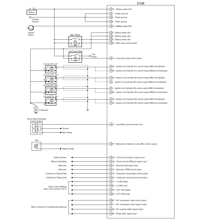
1 | Power ground | Chassis Ground |
2 | Battery power (B+) | Main Relay |
3 | Power ground | Chassis Ground |
4 | Battery power (B+) | Main Relay |
5 | Power ground | Chassis Ground |
6 | Battery power (B+) | Main Relay |
7 | - |
|
8 | - |
|
9 | - |
|
10 | - |
|
11 | - | |
12 | Engine speed signal output | Power Distribution Module (PDM) |
13 | - |
|
14 | - |
|
15 | - | |
16 | - |
|
17 | - |
|
18 | - |
|
19 | - |
|
20 | Electrical load [Wiper] signal input | Wiper [Low] Relay |
21 | - |
|
22 | - |
|
23 | - |
|
24 | - |
|
25 | Fuel Level Sensor (FLS) signal input | Fuel Level Sensor (FLS) |
26 | - |
|
27 | - |
|
28 | - |
|
29 | - |
|
30 | - |
|
31 | - |
|
32 | - |
|
33 | Malfunction Indication Lamp (MIL) control output | Malfunction Indication Lamp (MIL) |
34 | - | |
35 | - |
|
36 | - | |
37 | - | |
38 | - |
|
39 | - |
|
40 | - |
|
41 | - |
|
42 | - |
|
43 | - |
|
44 | - |
|
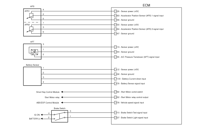
45 | Sensor ground | A/C Pressure Transducer (APT) |
46 | - |
|
47 | - | |
48 | - |
|
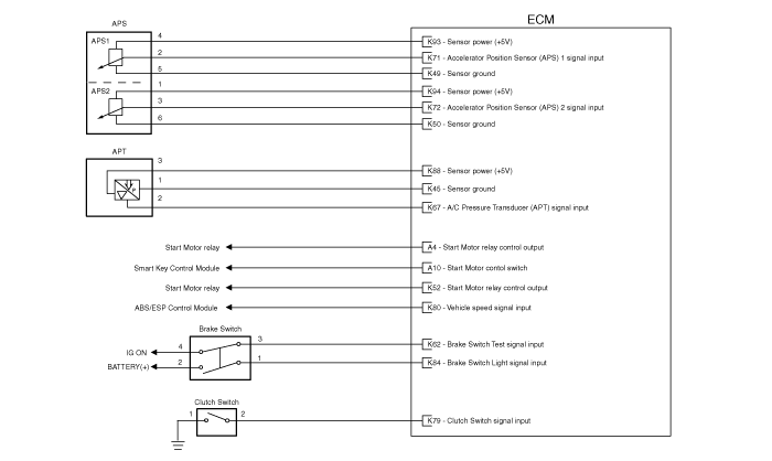
49 | Sensor ground | Accelerator Position Sensor (APS) 1 |
50 | Sensor ground | Accelerator Position Sensor (APS) 2 |
51 | Battery power (B+) | Ignition Switch |
52 | Start Motor relay control output | Start Motor relay |
53 | Cooling Fan Relay [High] control output | Cooling Fan Relay [High] |
54 | Cooling Fan Relay [Low] control output | Cooling Fan Relay [Low] |
55 | CCP CAN [High] | Other control module, Data Link Connector (DLC), |
56 | CCP CAN [Low] | Other control module, Data Link Connector (DLC), |
57 | - |
|
58 | - |
|
59 | - |
|
60 | - |
|
61 | - |
|
62 | Brake Test Switch signal input | Brake Switch |
63 | - |
|
64 | - | |
65 | - |
|
66 | - |
|
67 | A/C Pressure Transducer (APT) signal input | A/C Pressure Transducer (APT) |
68 | - | |
69 | Immobilizer communication line | Immobilizer control module |
70 | - |
|
71 | Accelerator Position Sensor (APS) 1 signal input | Accelerator Position Sensor (APS) 1 |
72 | Accelerator Position Sensor (APS) 2 signal input | Accelerator Position Sensor (APS) 2 |
73 | Battery power (B+) | Battery |
74 | Main Relay control output | Main Relay |
75 | Fuel Pump Relay control output | Fuel Pump Relay |
76 | LIN communication signal input | Bettery sensor |
77 | C-CAN [High] | Other control module, Data Link Connector (DLC), |
78 | C-CAN [Low] | Other control module, Data Link Connector (DLC), |
79 | Clutch switch signal input | Clutch switch |
80 | Vehicle speed signal input | ABS/ESP Control Unit |
81 | - |
|
82 | - |
|
83 | - |
|
84 | Brake Light Switch signal input | Brake Switch |
85 | - |
|
86 | - |
|
87 | - |
|
88 | Sensor power (+5V) | A/C Pressure Transducer (APT) |
89 | - |
|
90 | - | |
91 | - |
|
92 | - |
|
93 | Sensor power (+5V) | Accelerator Position Sensor (APS) 1 |
94 | Sensor power (+5V) | Accelerator Position Sensor (APS) 2 |
Pin No. | Description | Condition | Type | Level |
1 | Ignition Coil (Cylinder #1) control output | Idle | Pulse | Turn on: Max. 1.6V Turn off: Battery voltage |
Ignition Coil (Cylinder #4) control output | ||||
2 | Injector (Cylinder #1) control output | Idle | DC | Hi: Battery voltage |
LO: Max. 0.5V | ||||
48~50V | ||||
3 | - |
|
|
|
4 | Start motor relay control output |
|
|
|
5 | Heated Oxygen Sensor (HO2S) [Bank 1/Sensor 2] Heater control output | Relay OFF | DC | Battery voltage |
Relay ON | Max. 0.5V | |||
6 | Sensor ground | Idle | DC | Max. 0.5V |
7 | Heated Oxygen Sensor (HO2S) [Bank 1/Sensor 2] signal input | Idle | Analog DC | Min. 0.6V ~ Max. 1.0V |
8 | Knock Sensor (KS) signal input | Idle | Analog / Frequency | Freq.: Min. 8KHz ~ Max. 12KHz Level: Min. 180 ~ Max. 300mVpp |
9 | Intake Air Temperature Sensor (IATS) signal input | Idle | Analog | Min. 0.1V ~ Max. 4.7V |
10 | Start Motor contol switch | Switch ON | Digital | Battery voltage |
Switch OFF | Min. -0.3V ~ Max. 0.5V | |||
11 | Electrical load signal input | Idle | PWM | Freq.: 125Hz or 200Hz or 60Hz Duty rate 0% ~ 100% |
12 | Engine Coolant Temperature Sensor (ECTS) signal input | Idle | Analog | Min. 0.1V ~ Max. 4.7V |
13 | Throttle Position Sensor (TPS) 1 signal input | Idle | Analog | Min. 0.4V ~ Max. 4.5V |
14 | Sensor power (+5V) | IG OFF | DC | Max. 0.5V |
IG ON | Min. 4.75V ~ Max. 5.25V | |||
15 | ETC Motor [+] control output | Idle | PWM | Operating freq.: 1000Hz (estimated) |
Forward direction Turn on: Battery voltage Frewheeling: Max. 0.1V | ||||
Reverse direction Turn on: Max. 0.1V Frewheeling: Max. 0.1V | ||||
16 | Ignition Coil (Cylinder #3) control output | Idle | Pulse | Turn on: Max. 1.6V Turn off: Battery voltage |
Ignition Coil (Cylinder #2) control output | ||||
17 | Injector (Cylinder #3) control output | Idle | DC | Hi: Battery voltage |
LO: Max. 0.5V | ||||
48~50V | ||||
18 | Purge Control Solenoid Valve (PCSV) control output | Relay OFF | DC | Battery voltage |
Relay ON | Max. 1.76V | |||
19 | Variable Intake Solenoid (VIS) Valve control output | Relay OFF | DC | Battery voltage |
Relay ON | Max. 1.76V | |||
20 | - |
|
|
|
21 | - |
|
|
|
22 | Sensor shield ground | Idle | DC | Max. 0.5V |
23 | Sensor ground | Idle | DC | Max. 0.5V |
24 | Sensor ground | Idle | DC | Max. 0.5V |
25 | Sensor ground | Idle | DC | Max. 0.5V |
26 | - |
|
|
|
27 | Sensor ground | Idle | DC | Max. 0.5V |
28 | Throttle Position Sensor (TPS) 2 signal input | Idle | Analog | Min. 0.4V ~ Max. 4.5V |
29 | Sensor ground | Idle | DC | Max. 0.5V |
30 | ETC Motor [-] control output | Idle | PWM | Operating freq.: 1000Hz (estimated) |
Forward direction Turn on: max 0.1V Frewheeling: max 0.1V | ||||
Reverse direciton Turn on: Battery voltage Frewheeling: max 0.1V | ||||
31 | Ignition Coil (Cylinder #4) control output | Idle | Pulse | Turn on: Max. 1.6V Turn off: Battery voltage |
Ignition Coil (Cylinder #1) control output | ||||
32 | Injector (Cylinder #4) control output | Idle | DC | Hi: Battery voltage |
LO: Max. 0.5V | ||||
48~50V | ||||
33 | CVVT Oil Control (OCV) Valve [Bank 1/Intake] control output | Idle | PWM | Operating freq. range: 300Hz Duty rate: 0% ~ 100% |
34 | CVVT Oil Control (OCV) Valve [Bank 1/Exhaust] control output | Idle | PWM | Operating freq. range: 300Hz Duty rate: 0% ~ 100% |
35 | Sensor power (+5V) | IG OFF | DC | Max. 0.5V |
IG ON | Min. 4.75V ~ Max. 5.25V | |||
36 | - | |||
37 | - | |||
38 | - | |||
39 | Manifold Absolute Pressure Sensor (MAPS) signal input | Idle | Analog | Min. 0.8V ~ Max. 4.2V |
40 | Battery Sensor signal | Idle | Analog | Min. 0.3V ~ Max. 4.7V |
41 | Crankshaft Position Sensor (-) signal input | Idle | Frequency | Vpp Min. : 18V at Idle (for 1 rail) Vpp Max. : 90V at 5000rpm (for 1 rail) |
42 | Sensor ground | Idle | DC | Max. 0.5V |
43 | Sensor ground | Idle | DC | Max. 0.5V |
44 | - | |||
45 | - | |||
46 | Ignition Coil (Cylinder #2) control output | Idle | Pulse | Turn on: Max. 1.6V Turn off: Battery voltage |
Ignition Coil (Cylinder #3) control output | ||||
47 | Injector (Cylinder #2) control output | Idle | DC | Hi: Battery voltage |
LO: Max. 0.5V | ||||
48~50V | ||||
48 | - |
|
|
|
49 | Alternator PWM control output | IG OFF | PWM | Battery voltage |
IG ON | Max. 0.5V | |||
50 | Heated Oxygen Sensor (HO2S) [Bank 1/Sensor 1] Heater control output | Relay OFF | DC | Battery voltage |
Relay ON | Max. 0.5V | |||
51 | Heated Oxygen Sensor (HO2S) [Bank 1 / Sensor 1] signal input | Engine | Analog | Rich: 0.6 ∼ 1.0V |
Running | Lean: Max. 0.4V | |||
52 | - | |||
53 | Sensor ground | Idle | DC | Max. 0.5V |
54 | Sensor power (+5V) | IG OFF | DC | Max. 0.5V |
IG ON | Min. 4.75V ~ Max. 5.25V | |||
55 | Battery Current Direct Input | Idle | Analog | Min. 0.4V ~ Max. 4.5V |
56 | Crankshaft Position Sensor (+) signal input | Idle | Frequency | Vpp Min. : 18V at Idle (for 1 rail) Vpp Max. : 90V at 5000rpm (for 1 rail) |
57 | Camshaft Position Sensor (CMPS) [Bank 1/Exhaust] signal input | Idle | Pulse | Around 7Hz at 850rpm |
Around 25Hz at 3000rpm | ||||
58 | Camshaft Position Sensor (CMPS) [Bank 1/Intake] signal input | Idle | Pulse | Around 7Hz at 850rpm |
Around 25Hz at 3000rpm | ||||
59 | - |
| ||
60 | - |
Pin No. | Description | Condition | Type | Level |
1 | Power ground | Idle | DC | Max. 50mV |
2 | Battery power (B+) | IG OFF | DC | Max. 0.5V |
IG ON | Battery Voltage | |||
3 | Power ground | Idle | DC | Max. 50mV |
4 | Battery power (B+) | IG OFF | DC | Max. 0.5V |
IG ON | Battery Voltage | |||
5 | Power ground | Idle | DC | Max. 50mV |
6 | Battery power (B+) | IG OFF | DC | Max. 0.5V |
IG ON | Battery Voltage | |||
7 | - |
|
|
|
8 | - |
|
|
|
9 | - |
|
|
|
10 | - |
|
|
|
11 | - | |||
12 | Engine speed signal output | Idle | Frequency | Around 26Hz at 850rpm, idle |
Around 16Hz at 3000rpm | ||||
13 | - |
|
|
|
14 | - |
|
|
|
15 | - | |||
16 | - |
|
|
|
17 | - |
|
|
|
18 | - |
|
|
|
19 | - |
|
|
|
20 | Electrical load [Wiper] signal input | Idle | PWM | Battery voltage |
21 | - |
|
|
|
22 | - |
|
|
|
23 | - |
|
|
|
24 | - |
|
|
|
25 | Fuel Level Sensor (FLS) signal input | Idle | Analog | Min. 0.2V ~Max. 4.7V |
26 | - |
|
|
|
27 | - |
|
|
|
28 | - |
|
|
|
29 | - |
|
|
|
30 | - |
|
|
|
31 | - |
|
|
|
32 | - |
|
|
|
33 | Malfunction Indication Lamp (MIL) control output |
|
|
|
34 | - | |||
35 | - |
|
|
|
36 | - | |||
37 | - | |||
38 | - |
|
|
|
39 | - |
|
|
|
40 | - |
|
|
|
41 | - |
|
|
|
42 | - |
|
|
|
43 | - |
|
|
|
44 | - |
|
|
|
45 | Sensor ground | Idle | DC | Max. 50mV |
46 | - |
|
|
|
47 | - | |||
48 | - |
|
|
|
49 | Sensor ground | Idle | DC | Max. 50mV |
50 | Sensor ground | Idle | DC | Max. 50mV |
51 | Battery power (B+) | IG OFF | DC | Max. 0.5V |
IG ON | Battery Voltage | |||
52 | Start Motor relay control output | IG OFF | DC | Battery voltage |
IG ON | Min. -0.3V ~Max. 1.2V | |||
53 | Cooling Fan Relay [High] control output | IG OFF | DC | Battery voltage |
IG ON | Min. -0.3V ~Max. 1.2V | |||
54 | Cooling Fan Relay [Low] control output | IG OFF | PWM | Battery voltage |
IG ON | Min. -0.3V ~Max. 1.2V | |||
55 | CCP CAN [High] | RECESSIVE | Pulse | 2.0∼3.0V |
DOMINANT | 2.75∼4.5V | |||
56 | CCP CAN [Low] | RECESSIVE | Pulse | 2.0∼3.0V |
DOMINANT | 0~0.5V | |||
57 | - |
|
|
|
58 | - |
|
|
|
59 | - |
|
|
|
60 | - |
|
|
|
61 | - |
|
|
|
62 | Brake Test Switch signal input | Swich ON | Digital | Battery voltage |
Switch OFF | Min. -0.3V ~Max. 0.5V | |||
63 | - |
|
|
|
64 | - | |||
65 | - |
|
|
|
66 | - |
|
|
|
67 | A/C Pressure Transducer (APT) signal input | Idle | Analog | Min. 0.4V ~Max. 4.6V |
68 | - | |||
69 | Immobilizer communication line | When communicating after IG ON | Pulse | Hi: Min. 8.5V |
Lo: Max. 3.5V | ||||
70 | - |
|
|
|
71 | Accelerator Position Sensor (APS) 1 signal input | Idle | Analog | Min. 0.6V ~Max. 4.3V |
72 | Accelerator Position Sensor (APS) 2 signal input | Idle | Analog | Min. 0.3V ~Max. 2.1V |
73 | Battery power (B+) | IG OFF | DC | Min. -.03V ~Max. 1.2V |
IG ON | Battery Voltage | |||
74 | Main Relay control output | IG OFF | DC | Min. -.03V ~Max. 1.2V |
IG ON | Battery Voltage | |||
75 | Fuel Pump Relay control output | Relay OFF | DC | Battery Voltage |
Relay ON |
| Min. -.03V ~Max. 1.2V | ||
76 | LIN communication signal input | RECESSIVE | Pulse | Max 5.6V (at 14V) |
DOMINANT | Min 8.4V (at 14V) | |||
77 | C-CAN [High] | RECESSIVE | Pulse | 2.0∼3.0V |
DOMINANT | 2.75∼4.5V | |||
78 | C-CAN [Low] | RECESSIVE | Pulse | 2.0∼3.0V |
DOMINANT | 0~0.5V | |||
79 | Clutch switch signal input | Swich ON | Digital | Min. -0.3V ~Max. 0.5V |
Switch OFF | Battery voltage | |||
80 | Vehicle speed signal input | Idle | Frequency | Duty rate 40% ~ 60% |
81 | - |
|
|
|
82 | - |
|
|
|
83 | - |
|
|
|
84 | Brake Light Switch signal input | Swich ON | Digital | Battery voltage |
Switch OFF | Min. -0.3V ~Max. 0.5V | |||
85 | - |
|
|
|
86 | - |
|
|
|
87 | - |
|
|
|
88 | Sensor power (+5V) | IG OFF | DC | Max. 0.5V |
IG ON | 4.75 ~ 5.25V | |||
89 | - |
|
|
|
90 | - |
| ||
91 | - |
|
|
|
92 | - |
|
|
|
93 | Sensor power (+5V) | IG OFF | DC | Max. 0.5V |
IG ON | 4.75 ~ 5.25V | |||
94 | Sensor power (+5V) | IG OFF | DC | Max. 0.5V |
IG ON | 4.75 ~ 5.25V |
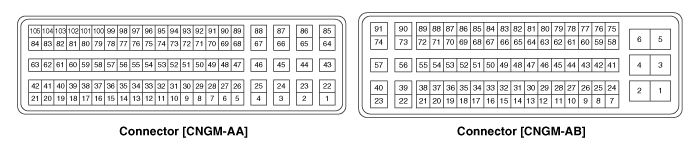
Pin No. | Description | Connected to |
1 | Ignition Coil (Cylinder #2) control output | Ignition Coil (Cylinder #2) [Without Immobilizer] |
Ignition Coil (Cylinder #3) control output | Ignition Coil (Cylinder #3) [With Immobilizer] | |
2 | - |
|
3 | - |
|
4 | - |
|
5 | - |
|
6 | - |
|
7 | - |
|
8 | - |
|
9 | - |
|
10 | - |
|
11 | Camshaft Position Sensor (CMPS) [Bank 1/Intake] signal input | Camshaft Position Sensor (CMPS) [Bank 1/Intake] |
12 | Sensor power (+5V) | Battery Sensor |
13 | Heated Oxygen Sensor (HO2S) [Bank 1/Sensor 1] signal input | Heated Oxygen Sensor (HO2S) [Bank 1/Sensor 1] |
14 | Heated Oxygen Sensor (HO2S) [Bank 1/Sensor 2] signal input | Heated Oxygen Sensor (HO2S) [Bank 1/Sensor 2] |
15 | - |
|
16 | - | |
17 | - |
|
18 | - |
|
19 | - |
|
20 | Sensor ground | Crankshaft Position Sensor (CKPS) |
21 | - | |
22 | Ignition Coil (Cylinder #4) control output | Ignition Coil (Cylinder #4) [Without Immobilizer] |
Ignition Coil (Cylinder #1) control output | Ignition Coil (Cylinder #1) [With Immobilizer] | |
23 | - |
|
24 | - |
|
25 | - |
|
26 | - |
|
27 | - |
|
28 | - |
|
29 | - |
|
30 | Sensor ground | Camshaft Position Sensor (CMPS) [Bank 1/Exhaust] |
31 | Camshaft Position Sensor (CMPS) [Bank 1/Exhaust] signal input | Camshaft Position Sensor (CMPS) [Bank 1/Exhaust] |
32 | Sensor ground | Camshaft Position Sensor (CMPS) [Bank 1/Intake] |
33 | Sensor power (+5V) | Throttle Position Sensor (TPS) 1,2 |
34 | Sensor ground | Heated Oxygen Sensor (HO2S) [Bank 1/Sensor 1] |
35 | Sensor ground | Heated Oxygen Sensor (HO2S) [Bank 1/Sensor 2] |
36 | - |
|
37 | - | |
38 | - |
|
39 | - |
|
40 | - |
|
41 | Crankshaft Position Sensor (CKPS) signal input | Crankshaft Position Sensor (CKPS) |
42 | - | |
43 | - |
|
44 | - |
|
45 | - |
|
46 | - |
|
47 | - |
|
48 | - |
|
49 | - |
|
50 | - |
|
51 | - |
|
52 | - |
|
53 | - |
|
54 | Sensor ground | Throttle Position Sensor (TPS) 1, 2 |
55 | - |
|
56 | Sensor shield ground | Knock Sensor (KS) |
57 | Immobilizer communication line | Immobilizer control module |
58 | Sensor ground | Battery Sensor |
59 | Intake Air Temperature Sensor (IATS) signal input | Intake Air Temperature Sensor (IATS) |
60 | - |
|
61 | Sensor ground | Manifold Absolute Pressure Sensor (MAPS) |
62 | Sensor ground | Engine Coolant Temperature Sensor (ECTS) |
63 | Engine Coolant Temperature Sensor (ECTS) signal input | Engine Coolant Temperature Sensor (ECTS) |
64 | Ignition Coil (Cylinder #3) control output | Ignition Coil (Cylinder #3) [Without Immobilizer] |
Ignition Coil (Cylinder #2) control output | Ignition Coil (Cylinder #2) [With Immobilizer] | |
65 | - |
|
66 | - |
|
67 | - |
|
68 | - |
|
69 | - |
|
70 | - |
|
71 | - |
|
72 | - |
|
73 | - |
|
74 | - |
|
75 | Throttle Position Sensor (TPS) 2 signal input | Throttle Position Sensor (TPS) 2 |
76 | - |
|
77 | Sensor ground | Knock Sensor (KS) |
78 | - |
|
79 | Battery Sensor signal | Battery Sensor |
80 | - |
|
81 | - |
|
82 | Manifold Absolute Pressure Sensor (MAPS) signal input | Manifold Absolute Pressure Sensor (MAPS) |
83 | - | |
84 | - | |
85 | Ignition Coil (Cylinder #1) control output | Ignition Coil (Cylinder #1) [Without Immobilizer] |
Ignition Coil (Cylinder #4) control output | Ignition Coil (Cylinder #4) [With Immobilizer] | |
86 | - |
|
87 | - |
|
88 | - |
|
89 | - |
|
90 | - |
|
91 | - |
|
92 | - |
|
93 | - |
|
94 | - |
|
95 | - |
|
96 | Throttle Position Sensor (TPS) 1 signal input | Throttle Position Sensor (TPS) 1 |
97 | - |
|
98 | Knock Sensor (KS) signal input | Knock Sensor (KS) |
99 | - |
|
100 | Battery Current Direct input | Battery Sensor |
101 | - |
|
102 | - |
|
103 | Sensor power (+5V) | Manifold Absolute Pressure Sensor (MAPS) |
104 | - | |
105 | - |
Pin No. | Description | Connected to |
1 | Power ground | Chassis Ground |
2 | Power ground | Chassis Ground |
3 | Battery power (B+) | Main Relay |
4 | Power ground | Chassis Ground |
5 | Battery power (B+) | Main Relay |
6 | Battery power (B+) | Main Relay |
7 | - |
|
8 | - |
|
9 | - |
|
10 | Brake Test Switch signal input | Brake Switch |
11 | A/C Compressor switch signal output | A/C Compressor switch |
12 | - |
|
13 | Sensor power (+5V) | A/C Pressure Transducer (APT) |
14 | - |
|
15 | Electrical load signal input | Alternator |
16 | Alternator PWM control output | Alternator |
17 | - |
|
18 | Cooling Fan Relay [High] control output | Cooling Fan Relay [High] |
19 | - | |
20 | ETC Motor [+] control output | ETC Motor |
21 | ETC Motor [-] control output | ETC Motor |
22 | Electrical load [Wiper] signal input | Wiper [Low] Relay |
23 | Injector (Cylinder #1) control output | Injector (Cylinder #1) |
24 | - |
|
25 | - |
|
26 | - |
|
27 | Brake Light Switch signal input | Brake Switch |
28 | A/C request switch signal output | Heater & A/C Control module |
29 | Sensor power (+5V) | Accelerator Position Sensor (APS) 1 |
30 | Sensor power (+5V) | Accelerator Position Sensor (APS) 2 |
31 | - |
|
32 | LIN communication signal input | Bettery sensor |
33 | Cooling Fan Relay [Low] control output | Cooling Fan Relay [Low] |
34 | - |
|
35 | - |
|
36 | - |
|
37 | Malfunction Indication Lamp (MIL) control output | Malfunction Indication Lamp (MIL) |
38 | - |
|
39 | - |
|
40 | Injector (Cylinder #3) control output | Injector (Cylinder #3) |
41 | Battery power (B+) | Ignition Switch |
42 | - |
|
43 | - |
|
44 | Sensor ground | A/C Pressure Transducer (APT) |
45 | A/C Pressure Transducer (APT) signal input | A/C Pressure Transducer (APT) |
46 | Sensor ground | Accelerator Position Sensor (APS) 1 |
47 | Sensor ground | Accelerator Position Sensor (APS) 2 |
48 | - |
|
49 | - | |
50 | - |
|
51 | - |
|
52 | Start Motor relay control output | Start Motor relay |
53 | Main Relay control output | Main Relay |
54 | - |
|
55 | - |
|
56 | - |
|
57 | Injector (Cylinder #4) control output | Injector (Cylinder #4) |
58 | - | |
59 | CCP CAN [Low] | Other control module, Data Link Connector (DLC), |
60 | C-CAN [Low] | Other control module, Data Link Connector (DLC), |
61 | - |
|
62 | - |
|
63 | Accelerator Position Sensor (APS) 1 signal input | Accelerator Position Sensor (APS) 1 |
64 | Accelerator Position Sensor (APS) 2 signal input | Accelerator Position Sensor (APS) 2 |
65 | Blower Max. signal input | Heater & A/C Control module |
66 |
|
|
67 | A/C Compressor Relay control output | A/C Compressor Relay |
68 | Variable Intake Solenoid (VIS) Valve control output | Variable Intake Solenoid (VIS) Valve |
69 | - |
|
70 | Fuel Pump Relay control output | Fuel Pump Relay |
71 | Engine speed signal output | Power Distribution Module (PDM) |
72 | - |
|
73 | - |
|
74 | Injector (Cylinder #2) control output | Injector (Cylinder #2) |
75 | Battery power (B+) | Main Relay |
76 | CCP CAN [High] |
|
77 | C-CAN [High] |
|
78 | Vehicle speed signal input | ABS/ESP Control Unit |
79 | - |
|
80 | - | |
81 | - | |
82 | Start Motor control switch | Smart key control module |
83 | - | |
84 | CVVT Oil Control (OCV) Valve [Bank 1/Exhaust] control output | CVVT Oil Control Valve (OCV) [Bank 1/Exhaust] |
85 | CVVT Oil Control (OCV) Valve [Bank 1/Intake] control output | CVVT Oil Control Valve (OCV) [Bank 1/Intake] |
86 | Purge Control Solenoid Valve (PCSV) control output | Purge Control Solenoid Valve (PCSV) |
87 | - | |
88 | - |
|
89 | - |
|
90 | Heated Oxygen Sensor (HO2S) [Bank 1/Sensor 2] Heater control output | Heated Oxygen Sensor (HO2S) [Bank 1/Sensor 2] |
91 | Heated Oxygen Sensor (HO2S) [Bank 1/Sensor 1] Heater control output | Heated Oxygen Sensor (HO2S) [Bank 1/Sensor 1] |
Pin No. | Description | Condition | Type | Level |
1 | Ignition Coil (Cylinder #2) control output | Idle | Pulse | Turn on: Max. 1.6V Turn off: Battery voltage |
Ignition Coil (Cylinder #3) control output | ||||
2 | - |
|
|
|
3 | - |
|
|
|
4 | - |
|
|
|
5 | - |
|
|
|
6 | - |
|
|
|
7 | - |
|
|
|
8 | - |
|
|
|
9 | - |
|
|
|
10 | - |
|
|
|
11 | Camshaft Position Sensor (CMPS) [Bank 1/Intake] signal input | Idle | Pulse | Around 7Hz at 850rpm |
Around 25Hz at 3000rpm | ||||
12 | Sensor power (+5V) | IG OFF | DC | Max. 0.5V |
IG ON | Min. 4.75V ~ Max. 5.25V | |||
13 | Heated Oxygen Sensor (HO2S) [Bank 1 / Sensor 1] signal input | Engine | Analog | Rich: 0.6 ∼ 1.0V |
Running | Lean: Max. 0.4V | |||
14 | Heated Oxygen Sensor (HO2S) [Bank 1/Sensor 2] signal input | Idle | Analog DC | Min. 0.6V ~ Max. 1.0V |
15 | - |
|
|
|
16 | - |
| ||
17 | - |
|
|
|
18 | - |
|
|
|
19 | - |
|
|
|
20 | Sensor ground | Idle | DC | Max. 50mV |
21 | - | |||
22 | Ignition Coil (Cylinder #4) control output | Idle | Pulse | Turn on: Max. 1.6V Turn off: Battery voltage |
Ignition Coil (Cylinder #1) control output | ||||
23 | - |
|
|
|
24 | - |
|
|
|
25 | - |
|
|
|
26 | - |
|
|
|
27 | - |
|
|
|
28 | - |
|
|
|
29 | - |
|
|
|
30 | Sensor ground | Idle | DC | Max. 50mV |
31 | Camshaft Position Sensor (CMPS) [Bank 1/Exhaust] signal input | Idle | Pulse | Around 7Hz at 850rpm |
Around 25Hz at 3000rpm | ||||
32 | Sensor ground | Idle | DC | Max. 50mV |
33 | Sensor power (+5V) | IG OFF | DC | Max. 0.5V |
IG ON | Min. 4.75V ~ Max. 5.25V | |||
34 | Sensor ground | Idle | DC | Max. 50mV |
35 | Sensor ground | Idle | DC | Max. 50mV |
36 | - |
|
|
|
37 | Sensor ground | Idle | DC | Max. 50mV |
38 | - |
|
|
|
39 | - |
|
|
|
40 | - |
|
|
|
41 | Crankshaft Position Sensor (+) signal input | Idle | Frequency | Vpp Min. : 18V at Idle (for 1 rail) Vpp Max. : 90V at 5000rpm (for 1 rail) |
42 | - | |||
43 | - |
|
|
|
44 | - |
|
|
|
45 | - |
|
|
|
46 | - |
|
|
|
47 | - |
|
|
|
48 | - |
|
|
|
49 | - |
|
|
|
50 | - |
|
|
|
51 | - |
|
|
|
52 | - |
|
|
|
53 | - |
|
|
|
54 | Sensor ground | Idle | DC | Max. 50mV |
55 | - |
|
|
|
56 | Sensor shield ground | Idle | DC | Max. 50mV |
57 | Immobilizer communication line | When communicating after IG ON | Pulse | Hi: Min. 8.5V |
Lo: Max. 3.5V | ||||
58 | Sensor ground | Idle | DC | Max. 50mV |
59 | Intake Air Temperature Sensor (IATS) signal input | Idle | Analog | Min. 0.1V ~ Max. 4.7V |
60 | - |
|
|
|
61 | Sensor ground | Idle | DC | Max. 50mV |
62 | Sensor ground | Idle | DC | Max. 50mV |
63 | Engine Coolant Temperature Sensor (ECTS) signal input | Idle | Analog | Min. 0.1V ~ Max. 4.7V |
64 | Ignition Coil (Cylinder #3) control output | Idle | Pulse | Turn on: Max. 1.6V Turn off: Battery voltage |
Ignition Coil (Cylinder #2) control output | ||||
65 | - |
|
|
|
66 | - |
|
|
|
67 | - |
|
|
|
68 | - |
|
|
|
69 | - |
|
|
|
70 | - |
|
|
|
71 | - |
|
|
|
72 | - |
|
|
|
73 | - |
|
|
|
74 | - |
|
|
|
75 | Throttle Position Sensor (TPS) 2 signal input | Idle | Analog | Min. 0.4V ~ Max. 4.5V |
76 | - |
|
|
|
77 | Sensor ground | Idle | DC | Max. 50mV |
78 | - |
|
|
|
79 | Battery Sensor signal | Idle | Analog | Min. 0.3V ~ Max. 4.7V |
80 | - |
|
|
|
81 | - |
|
|
|
82 | Manifold Absolute Pressure Sensor (MAPS) signal input | Idle | Analog | Min. 0.8V ~ Max. 4.2V |
83 | - | |||
84 | - | |||
85 | Ignition Coil (Cylinder #1) control output | Idle | Pulse | Turn on: Max. 1.6V Turn off: Battery voltage |
Ignition Coil (Cylinder #4) control output | ||||
86 | - |
|
|
|
87 | - |
|
|
|
88 | - |
|
|
|
89 | - |
|
|
|
90 | - |
|
|
|
91 | - |
|
|
|
92 | - |
|
|
|
93 | - |
|
|
|
94 | - |
|
|
|
95 | - |
|
|
|
96 | Throttle Position Sensor (TPS) 1 signal input | Idle | Analog | Min. 0.4V ~ Max. 4.5V |
97 | - |
|
|
|
98 | Knock Sensor (KS) signal input | Idle | Analog / Frequency | Freq.: Min. 8KHz ~ Max. 12KHz Level: Min. 180 ~ Max. 300mVpp |
99 | - |
|
|
|
100 | Battery Current Direct Input | Idle | Analog | Min. 0.4V ~ Max. 4.5V |
101 | - |
|
|
|
102 | - |
|
|
|
103 | Sensor power (+5V) | IG OFF | DC | Max. 0.5V |
IG ON | Min. 4.75V ~ Max. 5.25V | |||
104 | - | |||
105 | - |
|
Pin No. | Description | Condition | Type | Level |
1 | Power ground | Idle | DC | Max. 50mV |
2 | Power ground | Idle | DC | Max. 50mV |
3 | Battery power (B+) | IG OFF | DC | Max. 0.5V |
IG ON | Battery Voltage | |||
4 | Power ground | Idle | DC | Max. 50mV |
5 | Battery power (B+) | IG OFF | DC | Max. 0.5V |
IG ON | Battery Voltage | |||
6 | Battery power (B+) | IG OFF | DC | Max. 0.5V |
IG ON | Battery Voltage | |||
7 | - |
|
|
|
8 | - |
|
|
|
9 | - |
|
|
|
10 | Brake Test Switch signal input | Swich ON | Digital | Battery voltage |
Switch OFF | Min. -0.3V ~Max. 0.5V | |||
11 | A/C Compressor switch signal output | Swich ON | Digital | Battery voltage |
Switch OFF | Min. -0.3V ~Max. 0.5V | |||
12 | - |
|
|
|
13 | Sensor power (+5V) | IG OFF | DC | Max. 0.5V |
IG ON | Min. 4.75V ~ Max. 5.25V | |||
14 | - |
|
|
|
15 | Electrical load signal input | Idle | PWM | Battery voltage |
16 | Alternator PWM control output | IG OFF | PWM | Battery voltage |
IG ON | Max. 0.5V | |||
17 | - |
|
|
|
18 | Cooling Fan Relay [High] control output | IG OFF | DC | Battery voltage |
IG ON | Min. -0.3V ~Max. 1.2V | |||
19 | - | |||
20 | ETC Motor [+] control output | Idle | PWM | Operating freq.: 1000Hz (estimated) |
Forward direction Turn on: Battery voltage Frewheeling: Max. 0.1V | ||||
Reverse direction Turn on: Max. 0.1V Frewheeling: Max. 0.1V | ||||
21 | ETC Motor [-] control output | Idle | PWM | Operating freq.: 1000Hz (estimated) |
Forward direction Turn on: max 0.1V Frewheeling: max 0.1V | ||||
Reverse direciton Turn on: Battery voltage Frewheeling: max 0.1V | ||||
22 | Electrical load [Wiper] signal input | Idle | PWM | Battery voltage |
23 | Injector (Cylinder #1) control output | Idle | DC | Hi: Battery voltage |
LO: Max. 0.5V | ||||
48~50V | ||||
24 | - |
|
|
|
25 | - |
|
|
|
26 | - |
|
|
|
27 | Brake Light Switch signal input | Swich ON | Digital | Battery voltage |
Switch OFF | Min. -0.3V ~Max. 0.5V | |||
28 | A/C request switch signal output | Swich ON | Digital | Battery voltage |
Switch OFF | Min. -0.3V ~Max. 0.5V | |||
29 | Sensor power (+5V) | IG OFF | DC | Max. 0.5V |
IG ON | Min. 4.75V ~ Max. 5.25V | |||
30 | Sensor power (+5V) | IG OFF | DC | Max. 0.5V |
IG ON | Min. 4.75V ~ Max. 5.25V | |||
31 | - |
|
|
|
32 | LIN communication signal input | RECESSIVE | Pulse | Max. 5.6V (at 14V) |
DOMINANT | Min. 8.4V (at 14V) | |||
33 | Cooling Fan Relay [Low] control output | IG OFF | PWM | Battery voltage |
IG ON | Min. -0.3V ~Max. 1.2V | |||
34 | - |
|
|
|
35 | - |
|
|
|
36 | - |
|
|
|
37 | Malfunction Indication Lamp (MIL) control output |
|
|
|
38 | - |
|
|
|
39 | - |
|
|
|
40 | Injector (Cylinder #3) control output | Idle | DC | Hi: Battery voltage |
LO: Max. 0.5V | ||||
48~50V | ||||
41 | Battery power (B+) | IG OFF | DC | Max. 0.5V |
IG ON | Battery Voltage | |||
42 | - |
|
|
|
43 | - |
|
|
|
44 | Sensor ground | Idle | DC | Max. 50mV |
45 | A/C Pressure Transducer (APT) signal input |
|
|
|
46 | Sensor ground | Idle | DC | Max. 50mV |
47 | Sensor ground | Idle | DC | Max. 50mV |
48 | - |
|
|
|
49 | - | |||
50 | - |
|
|
|
51 | - |
|
|
|
52 | Start Motor contol switch | Switch ON | Digital | Battery voltage |
Switch OFF | Min. -0.3V ~ Max. 0.5V | |||
53 | Main Relay control output | IG OFF | DC | Min. -.03V ~Max. 1.2V |
IG ON | Battery Voltage | |||
54 | - |
|
|
|
55 | - |
|
|
|
56 | - |
|
|
|
57 | Injector (Cylinder #4) control output | Idle | DC | Hi: Battery voltage |
LO: Max. 0.5V | ||||
48~50V | ||||
58 | - | |||
59 | CCP CAN [Low] | RECESSIVE | Pulse | 2.0∼3.0V |
DOMINANT | 0~0.5V | |||
60 | C-CAN [Low] | RECESSIVE | Pulse | 2.0∼3.0V |
DOMINANT | 0~0.5V | |||
61 | - |
|
|
|
62 | - |
|
|
|
63 | Accelerator Position Sensor (APS) 1 signal input | Idle | Analog | Min. 0.6V ~Max. 4.3V |
64 | Accelerator Position Sensor (APS) 2 signal input | Idle | Analog | Min. 0.3V ~Max. 2.1V |
65 | Blower Max. signal input | Idle | Analog | Min. 0.5V ~Max. 4V |
66 | - |
|
|
|
67 | A/C Compressor Relay control output | Relay OFF | DC | Battery voltage |
Relay ON | Min. -0.3V ~Max. 1.2V | |||
68 | Variable Intake Solenoid (VIS) Valve control output |
|
|
|
69 | - |
|
|
|
70 | Fuel Pump Relay control output | Relay OFF | DC | Battery Voltage |
Relay ON |
| Min. -.03V ~Max. 1.2V | ||
71 | Engine speed signal output | Idle | Frequency | Around 26Hz at 850rpm, idle |
Around 16Hz at 3000rpm | ||||
72 | - |
|
|
|
73 | - |
|
|
|
74 | Injector (Cylinder #2) control output | Idle | DC | Hi: Battery voltage |
LO: Max. 0.5V | ||||
48~50V | ||||
75 | Battery power (B+) | IG OFF | DC | Max. 0.5V |
IG ON | Battery Voltage | |||
76 | CCP CAN [High] | RECESSIVE | Pulse | 2.0∼3.0V |
DOMINANT | 2.75∼4.5V | |||
77 | C-CAN [High] | RECESSIVE | Pulse | 2.0∼3.0V |
DOMINANT | 2.75∼4.5V | |||
78 | Vehicle speed signal input | Idle | Frequency | Duty rate 40% ~ 60% |
79 | - |
|
|
|
80 | - | |||
81 | - | |||
82 | Start Motor contol switch | Switch ON | Digital | Battery voltage |
Switch OFF | Min. -0.3V ~ Max. 0.5V | |||
83 | - | |||
84 | CVVT Oil Control (OCV) Valve [Bank 1/Exhaust] control output | Idle | PWM | Operating freq. range: 300Hz Duty rate: 0% ~ 100% |
85 | CVVT Oil Control (OCV) Valve [Bank 1/Intake] control output | Idle | PWM | Operating freq. range: 300Hz Duty rate: 0% ~ 100% |
86 | Purge Control Solenoid Valve (PCSV) control output | Relay OFF | DC | Battery voltage |
Relay ON | Max. 1.76V | |||
87 | - | |||
88 | - |
|
|
|
89 | - |
|
|
|
90 | Heated Oxygen Sensor (HO2S) [Bank 1/Sensor 2] Heater control output | Relay OFF | DC | Battery voltage |
Relay ON | Max. 0.5V | |||
91 | Heated Oxygen Sensor (HO2S) [Bank 1/Sensor 1] Heater control output | Relay OFF | DC | Battery voltage |
Relay ON | Max. 0.5V |