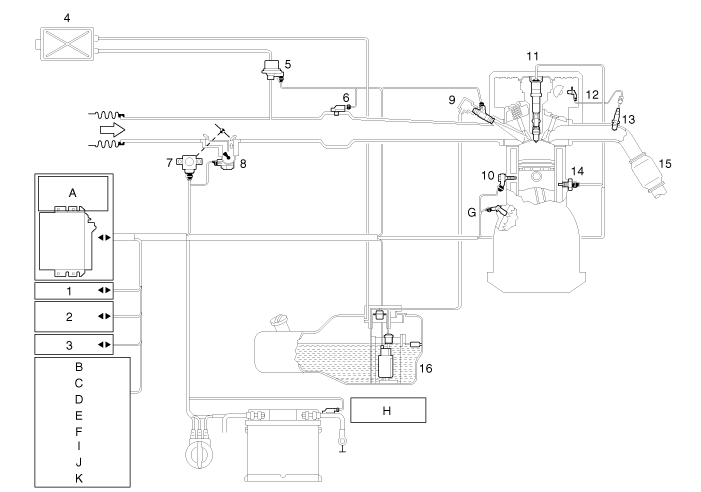

1. CAN 2. MIL lamp 3. Immobilizer 4. Canister 5. Purge control solenoid valve 6. Manifold absolute pressure sensor 7. Throttle position sensor (ETC module included) 8. ETC motor 9. Injector 10. Knock sensor 11. Iginition coil 12. Camshaft position sensor 13. Heated oxygen sensor 14. Engine coolant temperature sensor | 15. Catalyst 16. Low pressure pump A. Engine control module (ECM) B. Clutch switch C. Neutral switch D. Brake booster vacuum pressure sensor E. Alternator control F. Start motor G. Crankshaft position sensor H. Battery sensor I. DC/DC converter J. Hood switch K. Door / Seat belt switch (Driver's) |
The ISG system is strongly networked with the power management. In the event of battery replacement, disconnection of the battery terminal or after changing the engine management system, the reference data regarding the battery charge state and battery condition can be lost.
They are only available again a closed-circuit current measurement of approximate 4 hours in which the vehicle may not be wakened. In this time, the ISG system is inactive.