3.
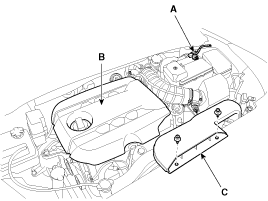
Remove the air duct (C).
Use fender covers to avoid damaging painted surfaces.
To avoid damage, unplug the wiring connectors carefully while holding the connector portion.
Mark all wiring and hoses to avoid misconnection.
For release the fuel system pressure before remove the engine assembly, start the engine without fuel pump relay. And then turn off the ignition switch after engine stops.
Disconnect the battery (-) cable (A).
Tightening torque :
3.9 ~ 5.9N.m (0.4 ~ 0.6kgf.m, 3.0 ~ 4.4lb-ft)
Remove the engine cover (B).
Remove the air duct (C).
Remove the air cleaner assembly.
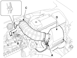
Disconnect the MAFS (Mass Air Flow Sensor) connector (A).
Remove the breather hose (B).
Diaconnect the air intake hose (C).
Tightening torque
Clamp bolt :
2.9 ~ 4.9N.m (0.3 ~ 0.5kgf.m, 2.2 ~ 3.6lb-ft)
Remove the air cleaner assembly (D).
Tightening torque :
7.8 ~ 9.8 N.m (0.8 ~ 1.0 kgf.m, 5.8 ~ 7.2 lb-ft)
When installing the air intake hose, confirm the assembly mark of hose to that of turbocharger.
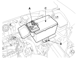
Remove the battery.
Disconnect the battery (+) terninal (A).
Tightening torque :
7.8 ~ 9.8 N.m (0.8 ~ 1.0 kgf.m, 5.8 ~ 7.2 lb-ft)
Remove the battery mounting bracket (B).
Tightening torque :
9.8 ~ 14.7 N.m (1.0 ~ 1.5 kgf.m, 7.2 ~ 10.8 Ib-ft)
Remove the battery (C) and insulator.
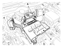
Disconnect the ECM connectors (A) and remove the ECM (B).
Tightening torque :
9.8 ~ 11.8 N.m (1.0 ~ 1.2 kgf.m, 7.2 ~ 8.7 lb-ft)
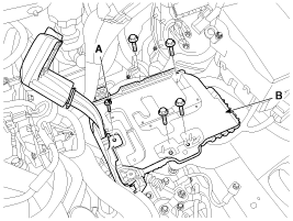
Loosen the battery “+” cable bracket mounting bolt (A) and then remove the battery tray (B).
Tightening torque :
9.8 ~ 14.7 N.m (1.0 ~ 1.5 kgf.m, 7.2 ~ 10.8 Ib-ft)
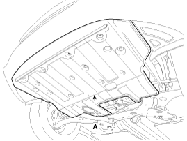
Remove the under cover (A).
Tightening torque :
7.8 ~ 11.8N.m (0.8 ~ 1.2kgf.m, 5.8 ~ 8.7lb-ft)
Loosen the drain plug (A) and drain the coolant. Open the radiator cap to make rapid draining.(Refer to Cooling system in this group)
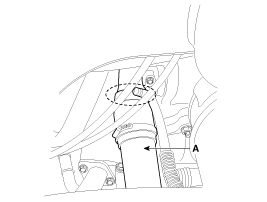
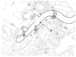
Remove the intercooler outlet hose (A) and inlet hose (B).
Tightening torque :
4.9 ~ 6.9N.m (0.5 ~ 0.7kgf.m, 3.6 ~ 5.1lb-ft)
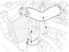
It is allowed to plaster cleaning liquid or alcohol on the connecting surfaces of hose and pipe, but all kinds of oil is prohibited.
The groove of hose must be in line with the protrusion of the throttle body.
The marking of hose must be in line with the stopper of the pipe.
The band must be located on the position mark of hose and must not over run it.
Tighten the torque control cap until it separated. If a torque control cap has already removed, tighten the screw at the specified torque.
Remove the radiator upper hose (A) and lower hose (B).
Install the radiator hoses as shown illustrations.
Remove the A/C refrigerant pipes (A). (Refer to A/C Compressor in HA group)
Remove the fuel hoses (A). (Refer to Fuel pump in FL Group)
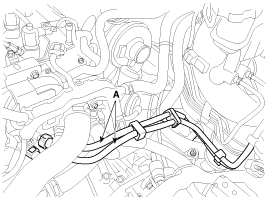
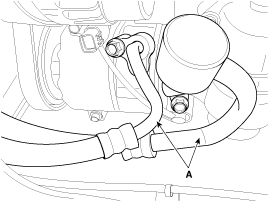
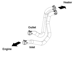
Disconnect the brake vacuum hose (A) and heater hoses (B).
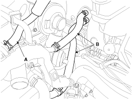
Install the heater hoses as shown illustrations.
Disconnect the engine wiring harness connectors and remove the wiring harness protectors.
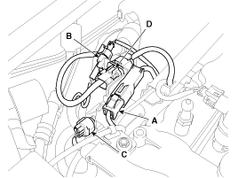
Fuel pressure regulator valve connector (A).
Fuel temperature sensor connector (B).
Oil pressure switch connector (C).
Variable swirl control actuator connector (D).
A/C compressor connector (D).
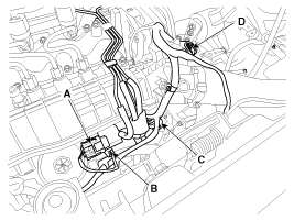
EGR cooler bypass solenoid valve connector (A).
VGT control solenoid valve connector (B).
Electric EGR control valve connector (C).
Air control valve connector (D).
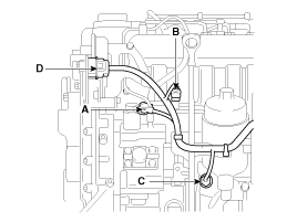
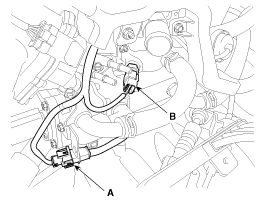
Crankshaft position sensor (CKPS) connector (A).
Eengine coolant temperature sensor (ECTS) connector (B).
Injector connectors (A).
Camshaft position sensor (CMPS) connector (B).
Rail pressure sensor connector (C).

Glow plug connector (A).
Exhaust gas temperature sensor connector (B).
Difference pressure sensor connector (C).
Lambda sensor connector (D).
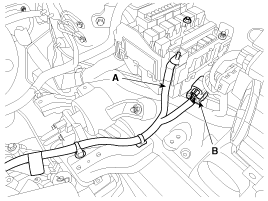
Disconnect the "+" cable (A) and the front connector (B).
Disconnect the transaxle wiring harness connectors, clutch release cylinder, control cables and ground line. (Refer to Transaxle in MT group)
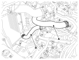
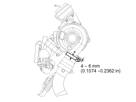
Remove the intercooler pipe and hose (A).
Tightening torque :
4.9 ~ 6.9N.m (0.5 ~ 0.7kgf.m, 3.6 ~ 5.1lb-ft)
It is allowed to plaster cleaning liquid or alcohol on the connecting surfaces of hose and pipe, but all kinds of oil is prohibited.
The groove of hose must be in line with the protrusion of the pipe or turbocharger.
The band must be located on the position mark of hose and must not run over it.
Tighten the torque control cap until it separated. If a torque control cap has already removed, tighten the screw at the specified torque.
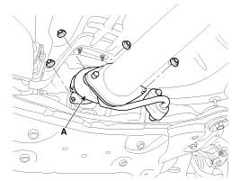
Remove the intercooler pipe (A) after lifting the vehicle.
Tightening torque :
6.9 ~ 10.8N.m (0.7 ~ 1.1kgf.m, 5.1 ~ 8.0lb-ft)
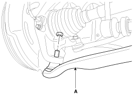
Remove the front muffler (A).
Tightening torque :
39.2 ~ 58.9N.m (4.0 ~ 6.0kgf.m, 28.9 ~ 43.4lb-ft)
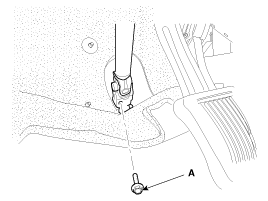
Remove the steering u-joint mounting bolt (A). (Refer to ST group)
Remove the front wheels. (Refer to SS group)
Remove the lower arms (A). (Refer to SS group – “Front lower arm”)
Remove the stabilizer bar links (A). (Refer to SS group – “Front stabilizer bar”)
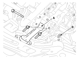
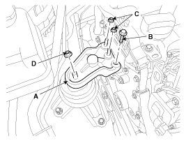
Remove the roll rod bracket (A).
Tightening torque
Nut (B) :
107.9 ~ 127.5N.m (11.0 ~ 13.0kgf.m, 79.6 ~ 94.0lb-ft)
Bolts (C) :
49.0 ~ 63.7N.m (5.0 ~ 6.5kgf.m, 36.1 ~ 47.0lb-ft)
Remove the tie rod ends (A). (Refer to ST group – “Steering gear box”)
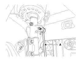
Remove the roll rod mounting support bracket (A).
Tightening torque :
44.1 ~ 58.8 N.m (4.5 ~ 6.0 kgf.m, 32.5 ~ 43.4 lb-ft)
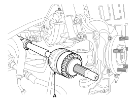
Disconnect the drive shafts (A) from the axle hubs. (Refer to DS group – “Front driveshaft”)
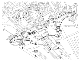
Support the sub frame (A) with a jack and then remove the sub frame bolts and nuts. (Refer to SS group)
Tightening torque
Sub frame mounting bolts & nuts:
156.9 ~ 176.5 N.m (16.0 ~ 18.0 kgf.m, 115.7 ~ 130.2 lb-ft)
Stay mounting bolts:
44.1 ~ 53.9 N.m (4.5 ~ 5.5 kgf.m, 32.5 ~ 39.8 lb-ft)
After removing the engine and transaxle mounting bolts and nuts, the engine and transaxle assembly may be fallen downward. Support them securely with floor jack.
Verify that the hoses and connectors are disconnected before removing the engine and transaxle assembly.
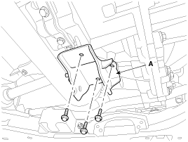
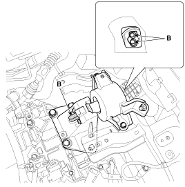
Remove the engine mounting support bracket (A).
Tightening torque :
Bolt (B), Nut (C) : 49.0 ~ 63.7 N.m (5.0 ~ 6.5 kgf.m, 36.2 ~ 47.0 lb-ft)
Nut (D) : 88.3 ~ 107.9N.m (9.0 ~ 11.0kgf.m, 65.1 ~ 79.6lb-ft)
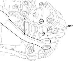
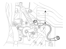
Disconnect the ground line (A), and then slowly loosen the transaxle mounting bolts (B).
Tightening torque :
88.3 ~ 107.9N.m (9.0 ~ 11.0kgf.m, 65.1 ~ 79.6lb-ft)
Remove the engine and transaxle assembly by lifting vehicle.
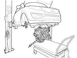
When remove the engine and transaxle assembly, be careful not to damage any surrounding parts or body components.
Installation is in the reverse order of removal.
Perform the followings :
Adjust shift cable.
Adjust throttle cable.
Refill engine with engine oil.
Refill transaxle with fluid.
Refill radiator and reservoir tank with engine coolant.
Place heater control knob on "HOT" position.
Bleed air from the cooling system.
Start engine and let it run until it warms up. (until the radiator fan operates 3 or 4 times.)
Turn Off the engine. Check the level in the radiator, add coolant if needed. This will allow trapped air to be removed from the cooling system.
Put radiator cap on tightly, then run the engine again and check for leaks.
Clean battery posts and cable terminals with sandpaper assemble them, then apply grease to prevent corrosion.
Inspect for fuel leakage.
After assemble the fuel line, turn on the ignition switch (do not operate the starter) so that the fuel pump runs for approximately two seconds and fuel line pressurizes.
Repeat this operation two or three times, then check for fuel leakage at any point in the fuel line.
