1.
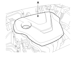
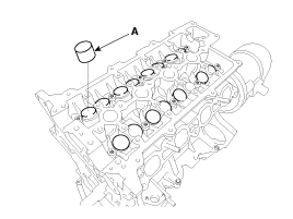
Remove the engine cover (A).
Engine removal is not required for this procedure.
Use fender covers to avoid damaging painted surfaces.
To avoid damaging the cylinder head, wait until the engine coolant temperature drops below normal temperature before removing it.
When handling a metal gasket, take care not to fold the gasket or damage the contact surface of the gasket.
To avoid damage, unplug the wiring connectors carefully while holding the connector portion.
Mark all wiring and hoses to avoid misconnection.
In case of removing the high pressure fuel pump, high pressure fuel pipe, delivery pipe, and injector, there may be injury caused by leakage of the high pressure fuel. So don’t do any repair work right after engine stops.
Remove the engine cover (A).
Disconnect the battery terminals (A).
Remove the air cleaner assembly.
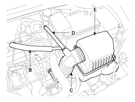
Remove the air duct (A)
Disconnect the breather hose (B) and the air intake hose (C), hose (D)
Remove the air cleaner assembly (E)
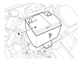
Remove the battery (A) after removing the mounting bracket.

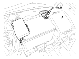
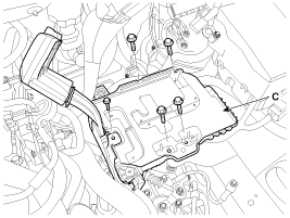
Disconnect the ECM connectors (A) and then remove the ECM (B) and battery tray (C).

Remove the RH front wheel.
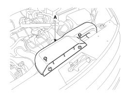
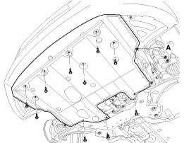
Remove the under covers (A).
Loosen the drain plug, and drain the engine coolant. Remove the radiator cap to help drain the coolant faster. (Refer to Cooling system in this group)
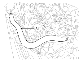
Disconnect the radiator upper hose (A) and lower hose (B).
Disconnect the wiring connectors and harness clamps, and remove the wiring and protectors from the cylinder head and intake manifold.
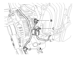
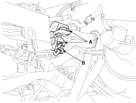
The A/C compressor switch connector (A), the alternator connector (B) and the cable from the alternator “B” terminal (C)
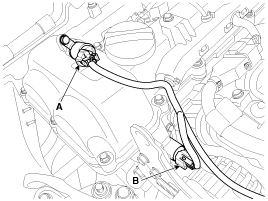
The intake OCV (Oil control valve) connector (A) and the exhaust OCV (Oil control valve) connector (B)
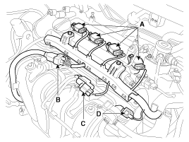
The ignition coil connectors (A), the injector extension connector (B), the VIS (Variable intake system) connector (C) and the PCSV (Purge control solenoid valve) connector (D)
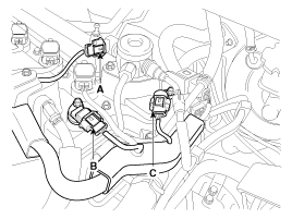
The FPCV (Fuel pressure control valve) connector (A), the intake CMPS (Camshaft position sensor) connector (B) and the exhaust CMPS (Camshaft position sensor) connector (C)
Disconnect the oxygen sensor connectors (A) and the condenser connector (B)
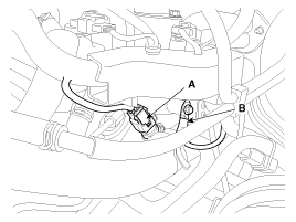
The ECTS (Engine coolant temperature sensor) connector (A) and the ground line (B)
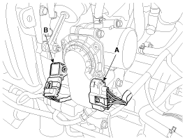
The ETC (Electronic throttle control) connector (A) and the MAPS (Manifold absolute pressure sensor) & IATS (Intake air temperature sensor) connector (B)
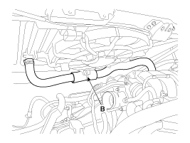
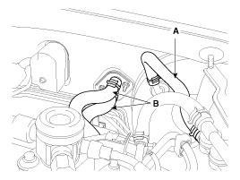
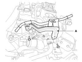
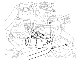
Disconnect the brake booster vacuum hose (A) and heater hose (B).
Disconnect the fuel hose (A), the PCV (Positive crankcase ventilation) hose (B) and the PCSV (Purge control solenoid valve) hose (C).
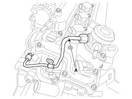
Remove the vacuum pipe assembly (A).
Remove the high pressure pipe (A). (Refer to FL group)
Remove the high pressure fuel pump (A) and the roller tappet (B). (Refer to FL group)
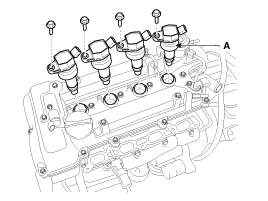
Remove the ignition coils (A).
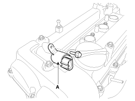
Remove the exhaust OCV (Oil control valve) (B).
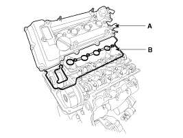
Remove the cylinder head cover (A) with gaskets (B).
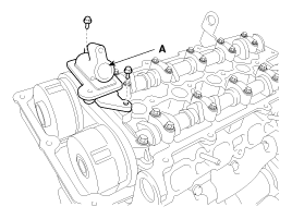
Remove the exhaust OCV (Oil control valve) adapter (A).
Remove the timing chain.
(Refer to Timing system in this group)
Remove the exhaust manifold assembly. (Refer to Intake and exhaust system in this group)
Remove the intake manifold module assembly. (Refer to Intake and exhaust system in this group)
Remove the intake CVVT assembly (A) and exhaust CVVT assembly (B).
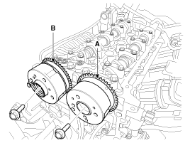
When removing the CVVT assembly bolt, prevent the camshaft from rotating by using a wrench at position (A).
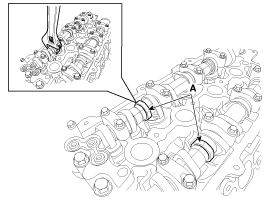
Remove the camshaft bearing caps (A) with the order below.
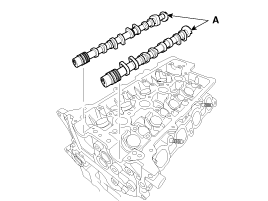
Remove the camshafts (A).
Remove the injector & rail assembly (A). (Refer to FL group)

Remove the water temperature control assembly (B) after disconnecting the throttle body cooling hose (A).
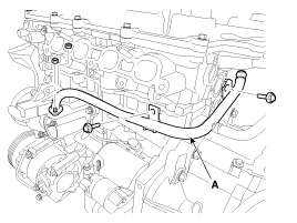
Remove the heater pipe (A).
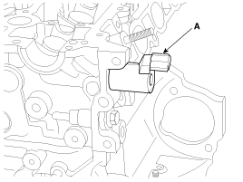
Remove the intake OCV (Oil Control Valve) (A).
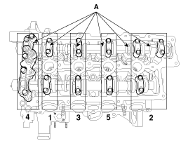
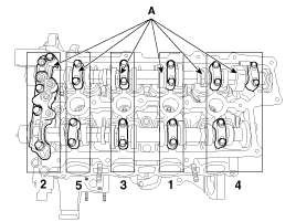
Remove the cylinder head bolts, then remove the cylinder head.
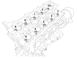
Uniformly loosen and remove the 10 cylinder head bolts, in several passes, in the sequence shown.
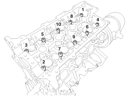
Head warpage or cracking could result from removing bolts in an incorrect order.
Lift the cylinder head from the cylinder block and put the cylinder head on wooden blocks.
Be careful not to damage the contact surfaces of the cylinder head and cylinder block.
Identify MLA(Mechanical lash adjuster), valves, valve springs as they are removed so that each item can be reinstalled in its original position.
Remove the MLAs (A).
When removing MLAs, mark all the MLAs for their rearrangement.
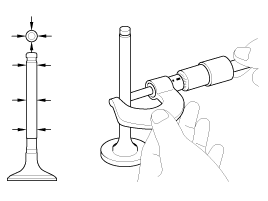
Remove the valves.
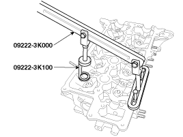
Using the SST (09222 - 3K000, 09222 - 3K100), compress the valve spring and remove the retainer lock.
Remove the spring retainer.
Remove the valve spring.
Remove the valve.
Remove the valve stem seal.
Using a magnetic pickup tool, remove the spring seat.
Do not reuse the valve stem seals.
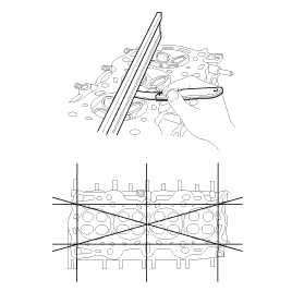
Inspect for flatness.
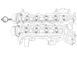
Using a precision straight edge and feeler gauge, measure the surface the contacting the cylinder block and the manifolds for warpage.
Flatness of cylinder head gasket surface
Standard :
Less than 0.05mm (0.0020in) for total area
Less than 0.02mm (0.0008in) for a section of 100mm (3.9370in) X 100mm (3.9370in)
Inspect for cracks.
Check the combustion chamber, intake ports, exhaust ports and cylinder block surface for cracks. If cracked, replace the cylinder head.
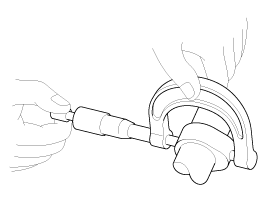
Inspect the valve stems and valve guides.
Using a caliper gauge, measure the inner diameter of valve guide.
Valve guide inner diameter :
5.500 ~ 5.512mm (0.2165 ~ 0.2170in)
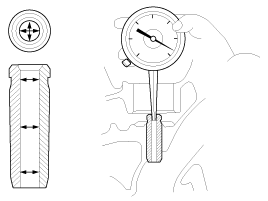
Using a micrometer, measure the outer diameter of valve stem.
Valve stem outer diameter
Intake : 5.465 ~ 5.480mm (0.2152 ~ 0.2157in)
Exhaust : 5.458 ~ 5.470mm (0.2149 ~ 0.2154in)
Subtract the valve stem outer diameter measurement from the valve guide inner diameter measurement.
Valve stem- to-guide clearance
Intake : 0.020 ~ 0.047mm (0.0008 ~ 0.0019in)
Exhaust : 0.030 ~ 0.054mm (0.0012 ~ 0.0021in)
If the clearance is greater than specification, replace the valve or the cylinder head.
Inspect the valves.
Check the valve is ground to the correct valve face angle.
Check that the surface of valve for wear.
If the valve face is worn, replace the valve.
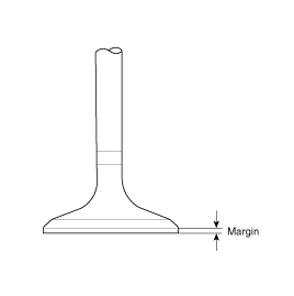
Check the valve head margin thickness.
If the margin thickness is less than minimum, replace the valve.
Margin
Standard
Intake : 1.10mm (0.0433in)
Exhaust : 1.26mm (0.0496in)
Check the length of valve.
Valve length
Standard
Intake : 93.15mm (3.6673 in)
Exhaust : 92.60mm (3.6457 in)
Check the surface of valve stem tip for wear.
If the valve stem tip is worn, replace the valve.
Inspect the valve seats.
Check the valve seat for evidence of overheating and improper contact with the valve face. If the valve seat is worn, replace the cylinder head.
Check the valve guide for wear. If the valve guide is worn, replace the cylinder head.
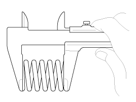
Inspect the valve springs.
Using a steel square, measure the out-of-square of valve spring.
Using a vernier calipers, measure the free length of valve spring.
Valve spring
Standard
Free height : 45.1mm (1.7756in)
Out of square : Less than 1.5˚
Inspect the cam height.
Using a micrometer, measure the cam height.
Cam height
Intake : 44.15mm (1.7382in)
Exhaust : 42.85mm (1.6870in)
If the cam lobe height is less than specified, replace the camshaft.
Check the cranshaft journal for wear.
If the journal is worn excessively, replace the camshaft.
Inspect the camshaft journal clearance.
Clean the bearing caps and camshaft journals.
Place the camshafts on the cylinder head.
Lay a strip of plastigage across each of the camshaft journal.
Install the bearing caps and tighten the bolts with specified torque.
Tightening torque :
1st step
M6 bolt :
5.9 N.m (0.6 kgf.m, 4.3 lb-ft)
M8 bolt :
9.8 N.m (1.0 kgf.m, 7.2 lb-ft)
2nd step
M6 bolts :
11.8 ~ 12.7N.m (1.2 ~ 1.3kgf.m, 8.7 ~ 9.4lb-ft)
M8 bolts :
18.6 ~ 22.6N.m (1.9 ~ 2.3kgf.m, 13.7 ~ 16.6lb-ft)
Do not turn the camshaft.
Remove the bearing caps.
Measure the plastigage at its widest point.
Bearing oil clearance
Standard : 0.027 ~ 0.058mm (0.0011 ~ 0.0023in)
Limit : 0.1mm ( 0.0039in)
If the oil clearance is greater than specified, replace the camshaft. If necessary, replace the bearing caps and cylinder head as a set.
Inspect the camshaft end play.
Install the camshafts.
Using a dial indicator, measure the end play while moving the camshaft back and forth.
Camshaft end play
Standard : 0.1 ~ 0.2mm (0.0039 ~ 0.0079in)
If the end play is greater than specified, replace the camshaft. If necessary, replace the bearing caps and cylinder head as a set.
Remove the camshafts.
Inspect the Continuous variable valve timing (CVVT) assembly.
Fix the Continuous variable valve timing (CVVT ) with its camshaft in a vice.
Check that the CVVT assembly will not turn. If it is not turned, it is in normal condition.
Apply vinyl tape to all the parts except the one hole.
Using an air gun, apply the pressure, 147.10kpa (1.5kg/cm², 21.33psi) in the hole. This makes the lock pin in maximum retarded state released.
Wrap around it with a shop rag, because the oil can splash out.
After releasing the pin, you can turn the CVVT assembly for advance by hand.
If there was too much air leakage, the pin can not be released.
Under the condition of 3), turn the CVVT assembly to the advance angle side with your hand.
Depending on the air pressure, the CVVT assembly will turn to the advance side.
Also, if the air pressure that was applied was insufficient because of the air leakage from the port, the lock pin may not release properly.
Except the position where the lock pin meets at the maximum delay angle, let the CVVT assembly turn back and forth and check the movable range and that there is no interference.
Standard : Movable smoothly in the range about 25˚
Turn the CVVT assembly with your hand counterclockwise and lock it at the maximum delay angle position.
Thoroughly clean all parts to be assembled.
Before installing the parts, apply fresh engine oil to all sliding and rotating surface.
Replace oil seals with new ones.
Install the valves.
Install the spring seats.
Using the SST (09222 - 2B100), push in a new oil seal.
Do not reuse old valve stem oil seals.
Incorrect installation of the seal could result in oil leakage past the valve guides.
Intake valve stem seals are different from exhaust ones in type. Do not reassembly ones in the other's places.
Install the valve, valve spring and spring retainer, after applying engine oil at the end of each valve.
When installing valve springs, the enamel coated side should face the valve spring retainer.
Using the SST (09222 - 3K000, 09222 - 3K100), compress the spring and install the retainer locks.
After installing the valves, ensure that the retainer locks are correctly in place before releasing the valve spring compressor.
When installing the SST, use the torque, 1.2kgf.m or less.
Lightly tap the end of each valve stem two or three times with the wooden handle of a hammer to ensure proper seating of the valve and retainer lock.
Install the MLA(Mechanical lash adjuster)s.
Check that the MLA (A) rotates smoothly by hand.
All the MLAs should be installed in its original position.
Thoroughly clean all parts to be assembled.
Always use a new cylinder head and manifold gasket.
Always use a new cylinder head bolt.
The cylinder head gasket is a metal gasket. Take care not to bend it.
Rotate the crankshaft, set the No.1 piston at TDC.
Install the cylinder head assembly.
Before installing, remove the hardened sealant from the cylinder block and cylinder head surface.
Before installing the cylinder head gasket, apply sealant on the upper surface of the cylinder block and reassemble the gasket within five minutes.
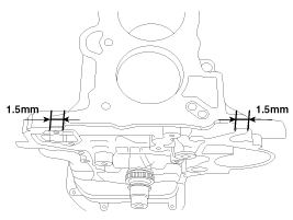
Refer to the illustration for applying sealant.
Width : 2.0 ~ 3.0mm(0.0787~0.1181in.)
Position : 1.0 ~ 1.5mm(0.0394~0.0591in.)
Specification : TB 1217H or LOCTITE 5900H
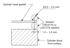
After installing the cylinder head gasket on the cylinder block, apply sealant on the upper surface of the cylinder head gasket and reassemble in five minutes.
Place the cylinder head carefully not to damage the gasket.
Install the cylinder head bolts with washers.
Tighten the 10 cylinder head bolts, in several passes, in the sequence shown.
Tightening torque :
29.4Nm (3.0kgf.m, 21.7lb-ft) + 90° + 90°
Always use new cylinder head bolts.
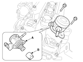
Install the oil control valve (OCV) (A).
Tightening torque :
9.8 ~ 11.8 N.m (1.0 ~ 1.2 kgf.m, 7.2 ~ 8.7 lb-ft)
Do not reuse the OCV when dropped.
Keep the OCV filter clean.
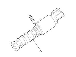
Do not hold the OCV sleeve (A) during servicing.
When the OCV is installed on the engine, do not move the engine with holding the OCV yoke.
Install the heater pipe (A).
Tightening torque
M6 bolt and nuts :
9.8 ~ 11.8N.m (1.0 ~ 1.2kgf.m, 7.2 ~ 8.7lb-ft)
M8 bolts :
18.6 ~ 23.5N.m (1.9 ~ 2.4kgf.m, 13.7 ~ 17.4lb-ft)
Install the water temperature control assembly (B) after connecting the throttle body cooling hose (A).
Tightening torque :
9.8 ~ 11.8N.m (1.0 ~ 1.2kgf.m, 7.2 ~ 8.7lb-ft)
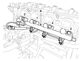
Install the injector & rail assembly (A).
Tightening torque :
18.6 ~ 23.5N.m (1.9 ~ 2.4kgf.m, 13.7 ~ 17.4lb-ft)
Install the intake and exhaust manifold.
(Refer to Intake and Exhaust system in this group)
Install the camshafts (A).
Before installing, apply engine oil on journals.
Do not make oil flow down to the front side of the cylinder head.
After installing, check the valve clearance.
Install the camshaft bearing caps (A) with the order below.
Tightening torque
1st step
M6 bolt :
5.9 N.m (0.6 kgf.m, 4.3 lb-ft)
M8 bolt :
9.8 N.m (1.0 kgf.m, 7.2 lb-ft)
2nd step
M6 bolts :
11.8 ~ 12.7N.m (1.2 ~ 1.3kgf.m, 8.7 ~ 9.4lb-ft)
M8 bolts :
18.6 ~ 22.6N.m (1.9 ~ 2.3kgf.m, 13.7 ~ 16.6lb-ft)
Install the intake CVVT assembly (A) and exhaust CVVT assembly (B).
Tightening torque :
63.7 ~ 73.5N.m (6.5 ~ 7.5kgf.m, 47.0 ~ 54.2lb-ft)
When installing the CVVT assembly bolt, prevent the camshaft from rotating by using a wrench at position (A).
Install the timing chain.
(Refer to Timing system in this group)
Install the OCV (Oil Control Valve) adapter (A).
Tightening torque :
9.8 ~ 11.8N.m (1.0 ~ 1.2kgf.m, 7.2 ~ 8.7lb-ft)
Keep the OCV adapter clean.
Make sure the O-rings on the front bearing cap are installed.
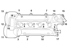
Install the cylinder head cover (A) with a new gasket (B).
Do not reuse the disassembled gasket.
Tighten the cylinder head cover bolts (A) with the order and steps.
Tightening torque
1st step:
3.9 ~ 5.9 N.m (0.4 ~ 0.6 kgf.m, 2.9 ~ 4.3 lb-ft)
2nd step:
7.8 ~ 9.8 N.m (0.8 ~ 1.0 kgf.m, 5.8 ~ 7.2 lb-ft)
Install the exhaust OCV (Oil control valve) (A).
Tightening torque :
9.8 ~ 11.8N.m (1.0 ~ 1.2kgf.m, 7.2 ~ 8.7lb-ft)
Do not reuse the OCV when dropped.
Keep the OCV filter clean.
Do not hold the OCV sleeve (A) during servicing.
When the OCV is installed on the engine, do not move the engine with holding the OCV yoke.
Install the ignition coils (A).
Tightening torque :
9.8 ~ 11.8N.m (1.0 ~ 1.2kgf.m, 7.2 ~ 8.7lb-ft)
Install the high pressure fuel pump (A) and the roller tappet (B). (Refer to FL group)
Tightening torque :
12.7 ~ 14.7N.m (1.3 ~ 1.5kgf.m, 9.4 ~ 10.8lb-ft)
Before installing the high pressure fuel pump, position the roller tappet in the lowest position (BDC) by rotating the crankshaft. Otherwise the installation bolts may be broken because of tension of the pump spring.
Do not use already used bolt again.
When tightening the installation bolts of the high pressure fuel pump, tighten in turn the bolts in small step (0.5 turns) after tightening them with hand-screwed torque.
Note that internal damage may occur when the component is dropped. In this case, use it after inspecting.
Apply engine oil to the O-ring (A) of the high pressure fuel pump, the roller tappet (B), and the protrusion (C). Also apply engine oil to the groove where the protrusion is installed.
Install the high pressure pipe (A). (Refer to FL group)
Tightening torque :
25.5 ~ 31.4N.m (2.6 ~ 3.2kgf.m, 18.8 ~ 23.1lb-ft)
Do not reuse the high pressure pipe.
Install the vacuum pipe assembly (A).
Tightening torque :
9.8 ~ 11.8N.m (1.0 ~ 1.2kgf.m, 7.2 ~ 8.7lb-ft)
Connect the fuel hose (A), the PCV (Positive crankcase ventilation) hose (B) and the PCSV (Purge control solenoid valve) hose (C).
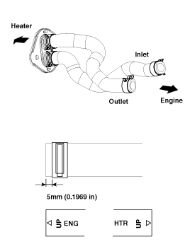
Connect the brake booster vacuum hose (A) and heater hose (B).
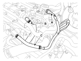
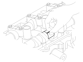
Install the heater hoses as shown illustrations.
Connect the wiring connectors and harness clamps, and remove the wiring and protectors from the cylinder head and intake manifold.
The A/C compressor switch connector (A), the alternator connector (B) and the cable from the alternator “B” terminal (C)
Tightening torque :
9.8 ~ 11.8N.m (1.0 ~ 1.2kgf.m, 7.2 ~ 8.7lb-ft)
The intake OCV (Oil control valve) connector (A) and the exhaust OCV (Oil control valve) connector (B)
The ignition coil connectors (A), the injector extension connector (B), the VIS (Variable intake system) connector (C) and the PCSV (Purge control solenoid valve) connector (D)
The FPCV (Fuel pressure control valve) connector (A), the intake CMPS (Camshaft position sensor) connector (B) and the exhaust CMPS (Camshaft position sensor) connector (C)
The oxygen sensor connectors (A) and the condenser connector (B).
The ECTS (Engine coolant temperature sensor) connector (A) and the ground line
The ETC (Electronic throttle control) connector (A) and the MAPS (Manifold absolute pressure sensor) & IATS (Intake air temperature sensor) connector (B)
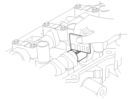
Connect the radiator upper hose (A) and lower hose (B).
Install the radiator hoses as shown illustrations.
Install the under covers (A).
Tightening torque :
7.8 ~ 11.8N.m (0.8 ~ 1.2kgf.m, 5.8 ~ 8.7lb-ft)
Install the battery tray (C).
Tightening torque :
8.8 ~ 13.7 N.m (0.9 ~ 1.4 kgf.m, 6.5 ~ 10.1 lb-ft)
Install the ECM (B) and then connect the ECM connectors (A).
Tightening torque :
9.8 ~ 11.8 N.m (1.0 ~ 1.2 kgf.m, 7.2 ~ 8.7 lb-ft)
Install the battery (A) after removing the mounting bracket.
Tightening torque :
8.8 ~ 13.7 N.m (0.9 ~ 1.4 kgf.m, 6.5 ~ 10.1 lb-ft)
Install the RH front wheel.
Install the air cleaner assembly.
Install the air cleaner assembly (D) and the air intake hose (C).
Tightening torque
Hose clamp bolt :
2.9 ~ 4.9N.m (0.3 ~ 0.5kgf.m, 2.2 ~ 3.6lb-ft)
Air cleaner assembly bolts :
7.8 ~ 9.8N.m (0.8 ~ 1.0kgf.m, 5.8 ~ 7.2lb-ft)
Connect the breather hose (B), hose (D).
Install the air duct (A).
Install the air intake hose while the plate of the hose clamp must be in line with the stopper of the hose.
Install the air intake hose while the groove of hose must be matched to the protrusion of the throttle body.
Connect the battery negative terminals (A).
Tightening torque
(+) terminal :
7.8 ~ 9.8N.m (0.8 ~ 1.0kgf.m, 5.8 ~ 7.2lb-ft)
(-) terminal (without battery sensor) :
7.8 ~ 9.8N.m (0.8 ~ 1.0kgf.m, 5.8 ~ 7.2lb-ft)
(-) terminal (with battery sensor) :
4.0 ~ 6.0N.m (0.4 ~ 0.6kgf.m, 3.0 ~ 4.4lb-ft)
Install the engine cover (A).
Install the engine cover.
Perform the following :
Adjust a shift cable.
Refill engine with engine oil.
Refill a transaxle with fluid.
Refill a radiator and a reservoir tank with engine coolant.
Clean battery posts and cable terminals and assemble.
Inspect for fuel leakage.
After assemble the fuel line, turn on the ignition switch (do not operate the starter) so that the fuel pump runs for approximately two seconds and fuel line pressurizes.
Repeat this operation two or three times, then check for fuel leakage at any point in the fuel line.
Bleed air from the cooling system.
Start engine and let it run until it warms up. (until the radiator fan operates 3 or 4 times.)
Turn Off the engine. Check the level in the radiator, add coolant if needed. This will allow trapped air to be removed from the cooling system.
Put radiator cap on tightly, then run the engine again and check for leaks.
