1.
Using a screwdriver or remover, remove the crash pad side cover (A).
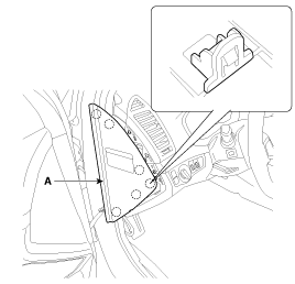
When prying with a flat-tip screwdriver, wrap it with protective tape, and apply protective tape around the related parts, to prevent damage.
Take care not to scratch the body surface.
Put on gloves to protect your hands.
Using a screwdriver or remover, remove the crash pad side cover (A).
After loosening the mounting screw, then remove the crash pad garnish [LH] (A).
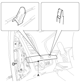
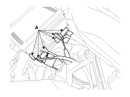
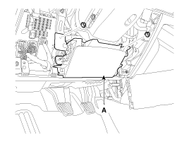
After loosening the mounting screws, then remove the cluster fascia panel (A).
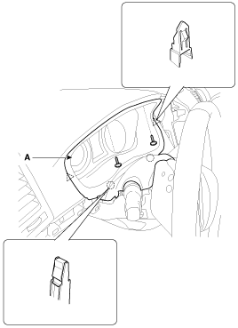
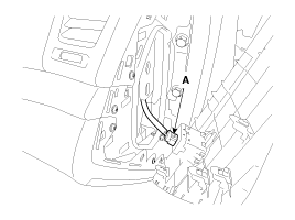
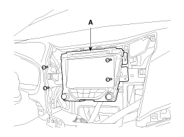
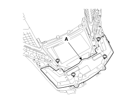
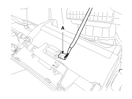
After loosening the mounting screws, then remove the Instrument cluster assembly(A).
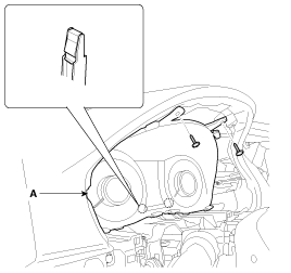
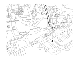
Disconnect the connector (A).
Install in the reverse order of removal.
Make sure the connector is connected properly.
Replace any damaged clips.
When prying with a flat-tip screwdriver, wrap it with protective tape, and apply protective tape around the related parts, to prevent damage.
Take care not to scratch the body surface.
Put on gloves to protect your hands.
Using a screwdriver or remover, remove the crash pad side cover (A).
After loosening the mounting screw, then remove the crash pad garnish [LH] (A).
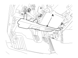
After loosening the mounting screws, then remove the crash pad lower panel (A).
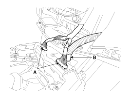
Disconnect the connectors (A) and diagnosis connector (B).
Using a screwdriver or remover, remove the crash pad side cover (A).
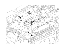
Disconnect pab cut off switch connector (A).
After loosening the mounting screw, then remove the crash pad garnish [RH] (A).
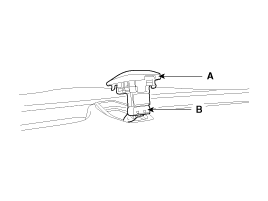
Disconnect the start/stop button connector (A).
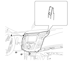
After loosening the mounting screws, then remove the center fascia panel (A).
Disconnect the connectors (A) and heater hose (B).
Install in the reverse order of removal.
Make sure the connectors are connected in properly.
Replace any damaged clips.
When prying with a flat-tip screwdriver, wrap it with protective tape, and apply protective tape around the related parts, to prevent damage.
Take care not to scratch the body surface.
Put on gloves to protect your hands.
Using a screwdriver or remover, remove the crash pad side cover (A).
After loosening the mounting screw, then remove the crash pad garnish [LH] (A).
After loosening the mounting screws, then remove the crash pad lower panel (A).
Disconnect the connectors (A) and diagnosis connector (B).
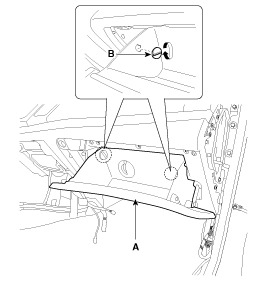
After loosening the mounting screws, then remove the crash pad under cover [LH] (A).
Disconnect the under cover lamp connector (A).
Install in the reverse order of removal.
Make sure the connectors are connected in properly.
Replace any damaged clips.
When prying with a flat-tip screwdriver, wrap it with protective tape, and apply protective tape around the related parts, to prevent damage.
Take care not to scratch the body surface.
Put on gloves to protect your hands.
Using a screwdriver or remover, remove the crash pad side cover (A).
After loosening the mounting screw, then remove the crash pad garnish [LH] (A).
After loosening the mounting screws, then remove the crash pad lower panel (A).
Disconnect the connectors (A) and diagnosis connector (B).
Using a screwdriver or remover, remove the crash pad side cover (A).
Disconnect pab cut off switch connector (A).
After loosening the mounting screw, then remove the crash pad garnish [RH] (A).
Disconnect the start/stop button connector (A).
After loosening the mounting screws, then remove the center fascia panel (A).
Disconnect the connectors (A) and heater hose (B).
After loosening the mounting screws, then remove the audio assembly (A).
Disconnect the audio connectors (A).
Install in the reverse order of removal.
Make sure the connectors are connected in properly.
Replace any damaged clips.
When prying with a flat-tip screwdriver, wrap it with protective tape, and apply protective tape around the related parts, to prevent damage.
Take care not to scratch the body surface.
Put on gloves to protect your hands.
Using a screwdriver or remover, remove the crash pad side cover (A).
After loosening the mounting screw, then remove the crash pad garnish [LH] (A).
After loosening the mounting screws, then remove the crash pad lower panel (A).
Disconnect the connectors (A) and diagnosis connector (B).
Using a screwdriver or remover, remove the crash pad side cover (A).
Disconnect pab cut off switch connector (A).
After loosening the mounting screw, then remove the crash pad garnish [RH] (A).
Disconnect the start/stop button connector (A).
After loosening the mounting screws, then remove the center fascia panel (A).
Disconnect the connectors (A) and heater hose (B).
After loosening the mounting screws, then remove the heater control unit (A).
Install in the reverse order of removal.
Make sure the connectors are connected in properly.
Replace any damaged clips.
When prying with a flat-tip screwdriver, wrap it with protective tape, and apply protective tape around the related parts, to prevent damage.
Take care not to scratch the body surface.
Put on gloves to protect your hands.
Disconnect the guide (B) from the glove box (A).
Disconnect the lift (A) from the glove box (B).
Disconnect the pin (A) and then remove the glove box (B).
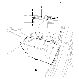
Push the pins (B) and then remove the crash pad under cover [RH] (A).
Disconnect the under cover lamp connector (A).
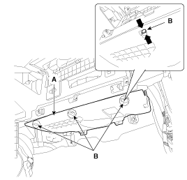
After loosening the mounting screws, then remove the glove box housing (A).
Disconnect the glove box lamp connector (A).
Install in the reverse order of removal.
Make sure the connectors are connected in properly.
Replace any damaged clips.
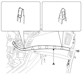
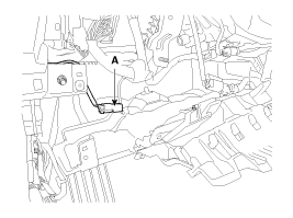
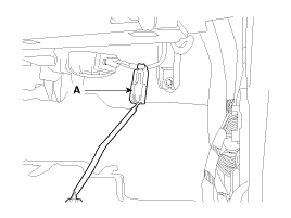
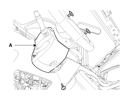
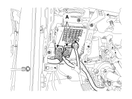
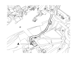
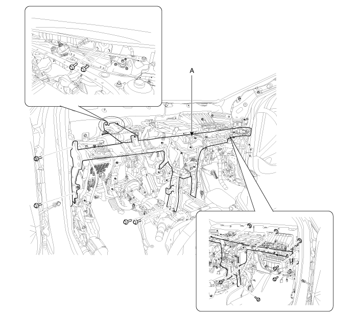
After loosening the mounting screws, then remove the shroud assembly (A).
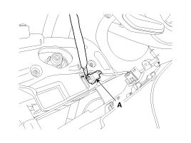
Disconnect the connector (A).
Install in the reverse order of removal.
Make sure the connectors are connected in properly.
Replace any damaged clips.
When prying with a flat-tip screwdriver, wrap it with protective tape, and apply protective tape around the related parts, to prevent damage.
Take care not to scratch the body surface.
Put on gloves to protect your hands.
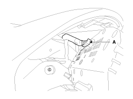
Using a screwdriver or remover, remove the crash pad side cover (A).
[Driver's]
Using a screwdriver or remover, remove the crash pad side cover (A).
[Passenger's]
Disconnect pab cut off switch connector (A).
Installation is the reverse the removal.
Make sure the connectors are connected in properly.
Replace any damaged clips.
When prying with a flat-tip screwdriver, wrap it with protective tape, and apply protective tape around the related parts, to prevent damage.
Take care not to scratch the body surface.
Put on gloves to protect your hands.
Remove the following items.
Front seat
(Refer to the BD group – “Front Seat”)
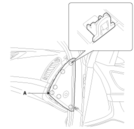
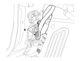
Front pillar trim
(Refer to the BD group – “Interior Trim”)
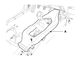
Floor console assembly
(Refer to the BD group – “Console”)
Front door scuff trim
(Refer to the BD group – “Interior Trim”)
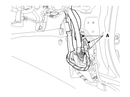
Cowl side trim
(Refer to the BD group- Interior Trim”)
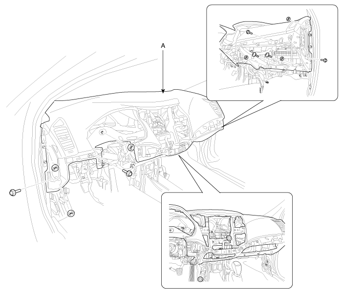
Crash pad side cover [LH, RH]
Crash pad garnish [LH, RH]
Crash pad lower panel
Crash pad under cover [LH, RH]
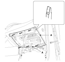
Cluster fascia panel & Cluster assembly
Center fascia panel
Audio assembly
Glove box & Glove box housing
Shroud assembly
Disconnect the steering column connectors.
(Refer to the ST group - "Steering Column and Shaft")
Down the steering column after loosening the mounting bolts.
(Refer to the ST group - "Steering Column and Shaft")
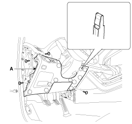
After loosening the mounting screws, then remove the crash pad center lower panel (A).
After loosening the mounting nuts, then remove the knee airbag (A).
(Refer to the RT group- "Knee Airbag (KAB) Module")
Disconnect the knee airbag harness connector (A).
(Refer to the RT group- "Knee Airbag (KAB) Module")
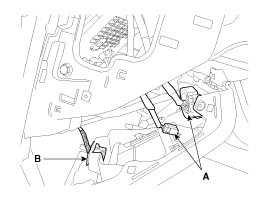
Disconnect the passenger`s airbag connectors (A).
Loosen the mounting bolts.
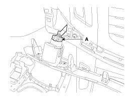
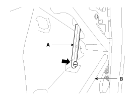
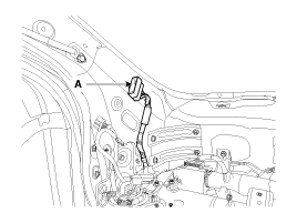
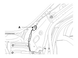
Using a screwdriver or remover, remove the photo sensor (A).
Disconnect the photo sensor connector (B).
After loosening the mounting bolts and nuts, screw, then remove the main crash pad assembly (A).
Install in the reverse order of removal.
Make sure the crash pad fits onto the guide pins correctly.
Before tightening the bolts, make sure the crash pad wire harnesses are not pinched.
Make sure the connectors are plugged in properly, and the antenna lead is connected properly.
Enter the anti- theft code for the radio, then enter the customer`s radio station presets.
When prying with a flat-tip screwdriver, wrap it with protective tape, and apply protective tape around the related parts, to prevent damage.
Take care not to scratch the body surface.
Put on gloves to protect your hands.
Remove the following items.
Front seat
(Refer to the BD group - "Front Seat")
Front pillar trim
(Refer to the BD group – “Interior Trim”)
Floor Console assembly
(Refer to the BD group - "Console")
Front door scuff trim
(Refer to the BD group – “Interior Trim”)
Cowl side trim
(Refer to the BD group - "Interior Trim")
Cowl top cover
(Refer to the BD group - "Cowl Top Cover")
Main crash pad
Disconnect the blower unit connectors.
(Refer to the HA group - "Air conditioning system, Heater, Blower")
After loosening the mounting bolt, then remove the console center air duct assembly (A).
Disconnect the multi box connectors (A).
[Driver's]
[Passenger's]
Disconnect the passenger compartment junction box connectors (A).
Disconnect the airbag control module (SRSCM) connector (A).
Disconnect the connector (A) and the mounting clips in the front pillar.
[Driver's]
[Passenger's]
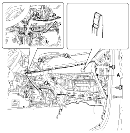
After loosening the mounting bolts and nuts, then remove the cowl cross bar assembly (A).
Install in the reverse order of removal.
Make sure the connectors are connected in properly.
Replace any damaged clips.
