STARTING CIRCUIT
Current data
1.

Monitor change of current data at IG key "START".

■ Reference data

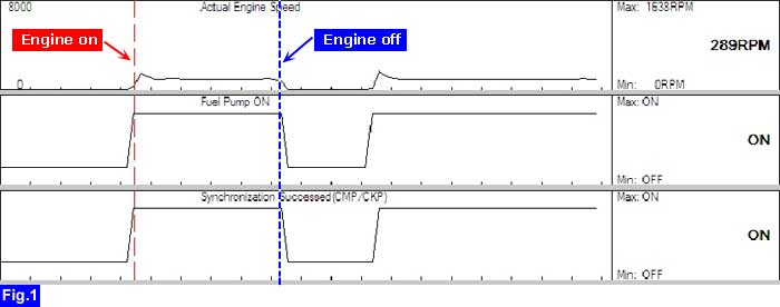
Fig.1) Normal current data at IG key "START"

caution

This current data is nothing but an example at certain condition. Thus, the real current data could be different from this example.

2.

Is the displayed current data normal?

▶ IG key "START" signal is normally inputted to ECM/PCM.

▶ Go to "ST signal inspection" procedure as below.

▶ Check if signal is normally inputted to "ON/START power" terminal of "ECM/PCM".

ST signal inspection
3.

IG key "OFF".

4.

Remove "START RELAY" and disconnect "ST" terminal of "START SOLENOID" harness connector.

5.

Connect jump wire directly to "Battery power" and "ST" terminal of "START RELAY" connector.

6.

Measure the voltage between "ST" terminal of "START SOLENOID" harness connector and battery (-) terminal.

■ Specification : B+

7.

Is the measured voltage value normally ?

▶ Go to "Start relay control inspection" procedure as below.

▶ Check for power supply at "Battery power supply" terminal of the "START RELAY" connector.

▶ Repair open/poor connection between "ST" terminal of "START RELAY" connector and "ST" terminal of "START SOLENOID" harness connector.

Start relay control inspection
8.

Remove "START RELAY".

9.

Measure the voltage between "Coil power supply" terminal of "START RELAY" connector and chassis ground at IG key "START".

■ Specification : B+

10.

Is the measured voltage value normally ?

▶ Repair/replace "START RELAY".

▶ Repair open/poor connection of "START RELAY" control/ground circuit.("Relay control" terminal)

▶ Repair open/poor connection of "START RELAY" coil power supply circuit.("Coil power supply" terminal)

Яндекс.Метрика