
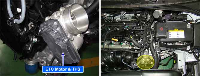
The Electronic Throttle Control(ETC) system is made of the components throttle body, Throttle Position Sensor(TPS)1&2 and Accelerator Position Sensor(APS) 1&2. The throttle body contains the actuator, the throttle plate and the throttle position sensor (potentiometer), which are integrated in one housing. The actuator consists of a DC motor with a two-stage gear. The opening angle of the throttle valve is detected by the throttle position sensor which is mounted on the throttle body. And it provides feedback to the PCM to control the throttle motor in order to control the throttle valve opening angle properly in response to the driving condition.
PCM sets DTC P2119 if the PCM detects TPS adaptation procedure is abnormal.
Item | Detecting Condition | Possible Cause | |
DTC Strategy | Case1 |
•
TPS adaptation Lower position check | 1. Poor connection or damaged harness 2. Faulty ETC Motor |
Case2 |
•
TPS adaptation error low return spring check | ||
Case3 |
•
TPS adaptation upper position check | ||
Case4 |
•
TPS adaptation error upper return spring check | ||
Case5 |
•
TPS start check error in spring check | ||
Case6 |
•
TPS start check error in limp-home-check | ||
Enable Conditions | Case1 |
•
During TPS adaptation
•
TPS setpoint = 11.9% | |
Case2,4 |
•
During TPS adaptation | ||
Case3 |
•
During TPS adaptation
•
TPS setpoint = 29% | ||
Case5 |
•
During TPS start check
•
TPS setpoint = 24.2% | ||
Case6 |
•
During TPS start check
•
No engine start condition | ||
Threshold Value | Case1 |
•
Throttle position for the lower return spring check is not reached within a limit maximum time(Difference between throttle position and setpoint > 0.48%°) | |
Case2 |
•
When ETC power stage is off, Throttle can not return by spring power in the limp-home position within a limit maximum time(Difference between Throttle position and adapted voltage in limphome position > 0.18 V) | ||
Case3 |
•
Throttle position for the upper return spring check is not reached within a limit maximum time(Difference between throttle position and setpoint > 0.48%) | ||
Case4 |
•
When ETC power stage is off, Throttle cannot return by spring power in the limp-home position within a limit maximum time(Difference between Throttle position and adapted voltage in limphome position > 0.18 V) | ||
Case5 |
•
Throttle flap cannot reach the setpoint within the hysteresis within a limit maximum time(Difference between throttle position and requested position > 0.48%) | ||
Case6 |
•
When ETC power stage is off, Throttle cannot return by spring power in the limp-home position within a limit maximum time(Difference between Throttle position and adapted voltage in limphome position > 0.18V) | ||
Diagnostic Time |
•
0.8~1.2 sec. | ||
Limp-Home |
•
Forced limited RPM mode : The PCM limits engine speed to 1500rpm
•
Electrical check of the ETC system is prohibited | ||
MIL On Condition |
•
Immediate | ||
