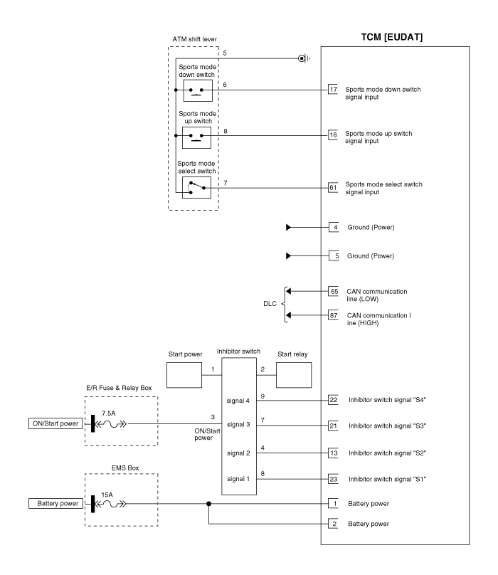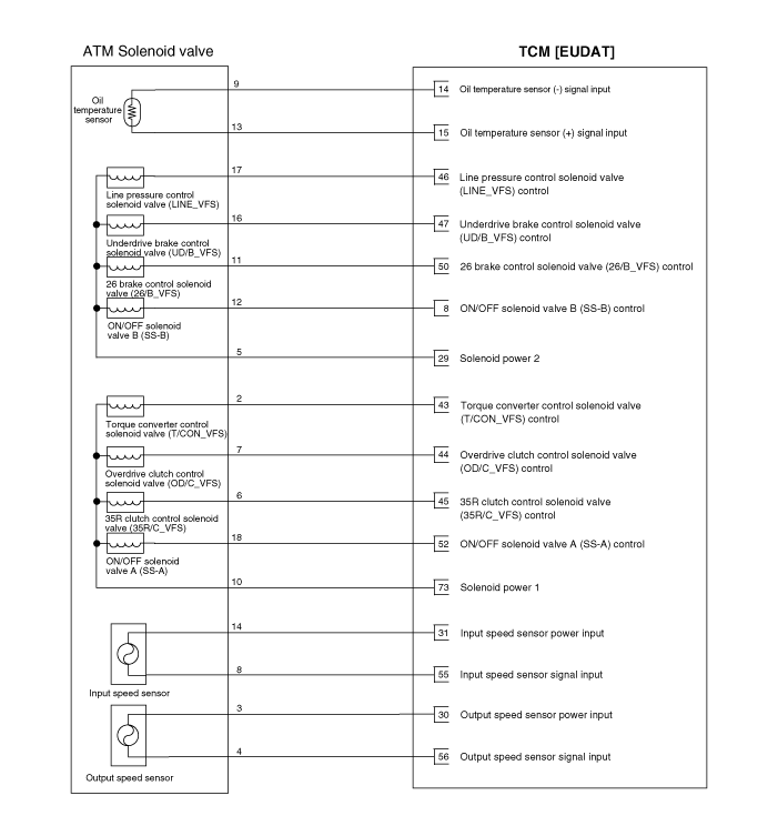
Pin | Description | Pin | Description |
1 | Power(VB) | 48 | ㅡ |
2 | Power(VB) | 49 | ㅡ |
3 | Ignition switch | 50 | 26 brake control solenoid valve |
4 | Ground (Power) | 51 | ㅡ |
5 | Ground (Power) | 52 | ON/OFF solenoid valve A(SS-A) |
6 | ㅡ | 53 | ㅡ |
7 | ㅡ | 54 | ㅡ |
8 | ON/OFF solenoid valve B(SS-B) | 55 | Input speed sensor signal |
9 | ㅡ | 56 | Output speed sensor signal |
10 | ㅡ | 57 | ㅡ |
11 | ㅡ | 58 | ㅡ |
12 | ㅡ | 59 | ㅡ |
13 | Inhibitor switch signal "S2" | 60 | ㅡ |
14 | Oil temperature sensor (+) | 61 | Sports mode select switch |
15 | Oil temperature sensor(-) | 62 | ㅡ |
16 | Sports mode up switch | 63 | ㅡ |
17 | Sport mode down switch | 64 | ㅡ |
18 | ㅡ | 65 | CAN (LOW) |
19 | ㅡ | 66 | ㅡ |
20 | ㅡ | 67 | ㅡ |
21 | Inhibitor switch signal "S3" | 68 | ㅡ |
22 | Inhibitor switch signal "S4" | 69 | ㅡ |
23 | Inhibitor switch signal "S1" | 70 | ㅡ |
24 | ㅡ | 71 | ㅡ |
25 | ㅡ | 72 | ㅡ |
26 | ㅡ | 73 | Solenoid supply power 2 |
27 | ㅡ | 74 | ㅡ |
28 | ㅡ | 75 | ㅡ |
29 | Solenoid supply power 1 | 76 | ㅡ |
30 | Output speed sensor power | 77 | ㅡ |
31 | Input speed sensor power | 78 | ㅡ |
32 | ㅡ | 79 | ㅡ |
33 | ㅡ | 80 | ㅡ |
34 | ㅡ | 81 | ㅡ |
35 | ㅡ | 82 | ㅡ |
36 | ㅡ | 83 | ㅡ |
37 | ㅡ | 84 | ㅡ |
38 | ㅡ | 85 | ㅡ |
39 | ㅡ | 86 | ㅡ |
40 | ㅡ | 87 | CAN (High) |
41 | ㅡ | 88 | ㅡ |
42 | ㅡ | 89 | ㅡ |
43 | Torque converter control solenoid valve | 90 | ㅡ |
44 | Overdrive clutch control solenoid valve | 91 | ㅡ |
45 | 35R clutch control solenoid valve | 92 | ㅡ |
46 | Line pressure control solenoid valve | 93 | ㅡ |
47 | Underdrive brake control solenoid valve | 94 | ㅡ |
Pin | Description | Condition | Inoutput value | |
Type | Level | |||
23 | P range position switch 1 | ON | Digital | Max. ≤ 16.0V |
13 | P range position switch 2 | OFF | ||
21 | P range position switch 3 | ON | Min. ≥ 7.0V | |
22 | P range position switch 4 | ON | ||
23 | R range position switch 1 | OFF | Digital | Max. ≤ 16.0V |
13 | R range position switch 2 | OFF | ||
21 | R range position switch 3 | OFF | Min. ≥ 7.0V | |
22 | R range position switch 4 | ON | ||
23 | N range position switch 1 | ON | Digital | Max. ≤ 16.0V |
13 | N range position switch 2 | ON | ||
21 | N range position switch 3 | OFF | Min. ≥ 7.0V | |
22 | N range position switch 4 | ON | ||
23 | D range position switch 1 | ON | Digital | Max. ≤ 16.0V |
13 | D range position switch 2 | OFF | ||
21 | D range position switch 3 | OFF | Min. ≥ 7.0V | |
22 | D range position switch 4 | OFF | ||
14 | Oil temperature sensor signal (+) | - | Analog | Min.: 0 V |
15 | Oil temperature sensor signal (-) | - | Max.: 5.1 V | |
61 | Sports mode select | ON | Digital | Max. Low level threshold value ≤ 2.0 V |
16 | Up shift switch | OFF | Min. High level threshold value ≥ 4.0 V | |
17 | Down shift switch | OFF |
| |
56 | Output speed sensor | Revolution | Pulse | Max. frequency : 9 kHz |
Min. frequency: > 0 Hz | ||||
55 | Input speed sensor | Revolution | Min. High Pulse: ≥ 25 µs | |
Min. Low Pulse: ≥ 25 µs | ||||
29 | Solenoid supply power 1 | - | Output |
|
46 | Line pressure control solenoid valve | Variable duty | VFS | Max. Output current (TCM): 850 mA |
47 | Underdrive brake control solenoid valve | Variable duty | Min. Output current (TCM): 50 mA | |
50 | 26 brake control solenoid valve | Variable duty |
| |
73 | Solenoid supply power 2 | - | Output |
|
43 | Torque converter control solenoid valve | Variable duty | VFS | Max. Output current (TCM): 850 mA |
44 | Overdrive clutch control solenoid valve | Variable duty | Min. Output current (TCM): 50 mA | |
45 | 35R clutch control solenoid valve | Variable duty |
| |
52 | ON/OFF solenoid valve A(SS-A) | ON/OFF | PWM | Output current : 0.7A |
8 | ON_OFF solenoid valve B | ON/OFF | ||